8 pin connector. Speed \u200b\u200bof the computer power supply connectors. Power connector peripheral devices
I was lucky enough to purchase the NVIDIA GTX 780 video card instead of its old NVIDIA GTX 560. The joy of buying was not long, because The video card refused to bring into my case. Although this problem is treated quickly with the help of grinder and direct hands)))

The next and main problem was the presence of two 8 PIN connectors on the video card and their absence on the power supply. I have a block of 700 W but it goes 2 * 6 PIN.
First, refer to the theory, what is this 8-pin connector? In fact, it is the same 6-pin connector only with the addition of two additional contacts "Earth". It is necessary to give additional power on the video card on the bus 12V, which in turn is necessary for powerful video adapters, as well as for overclocking and using standard technologies, such as AMD OverDrive.

After reading the "smart" forums, came to the conclusion that, in principle, the use of additional contacts is not mandatory, although desirable.
When trying to start the system, the video adapter issued an error about the lack of power, and refused to start the PC. It became clear that you need to connect the eight pin connector. In principle, there are adapters from 6 to 8 contacts, but firstly they cost money, and secondly, you need to wait until they are brought, but to put a new vidyuhu "burned" right now))).
Having studied the proposed adapter it became clear that two additional contacts simply duplicate from the available.
 It was also necessary to get a connector to connect to the video card. For this purpose, an existing eight contact adapter for powering the processor has become excellent. I just saw the necessary parts that are suitable in the video card.

Now it was necessary to connect the connector to the power unit. It would be possible to connect to 6 PIN connectors, but I did not touch them, and it cut off one not used SATA power connector and took two wires of the "Earth" from there, and the rest threw. And that's what happened.
Standard power sources running from 220V, and may also have a mechanical input voltage switch 110V or 220V AC (alternating current). A computer power supply is designed to convert the variable tension of 220 volts DC to a constant current +12 volt, + 5 volt, + 3.3 volt, then the direct current goes on the power components of the computer. 3.3 and 5 volts are usually used in digital circuits, and 12 volts are used to start the drive engines and fans.
ATX 20 and 24 Contact Main Power Cable Connector
A 24-pin 12-volt ATX power connector can only be connected in one direction in the motherboard slot. If you carefully look at the image at the top of this page, you will see that contacts have a unique form that corresponds to only one direction on the motherboard. The initial ATX standard supported a 20-pin connector with a very similar pinout, which is a 24-pin connector, but the conclusions 11, 12, 23 and 24 are missed. This means that a newer 24-pin power supply is useful for system boards that require more power. On the modern motherboards can stand only 2 types of connectors 20-pin main power connector or 24-pin main power connector.
 Many power supplies are supplied with 20 + 4 contact chips, which is compatible with 20 and 24-pin PET Slots of motherboards. In 20 + 4, the power cable consists of two parts: 20-pin, and 4-pin chips. If you disconnect the two parts separately, then you can connect a 20-pin connector, and if you connect two chips 20 + 4 power cables together, you will have a 24-pin power cable that can be connected to a 24-pin motherboard power slot. .
ATX 4-pin power connector

Molex 4-pin peripheral power cable connector

Four contact peripheral power cable. It was used for floppy disks and hard drives and is still very widely used. You do not have to worry about installing this connector, it cannot be installed incorrect. People often use the term "4-pin Molex power cable" or "4-pin Molex" to designate.
SATA 15.- Contact K. abel nutrition

SATA was entered to update the ATA interface (also called IDE) for a more advanced design. The SATA interface includes as a data cable and a power cable. The power cable replaces the old 4-pin peripheral cable and adds support for 3.3 volts (if fully implemented).
8-pin EPS and +12 volt power connector
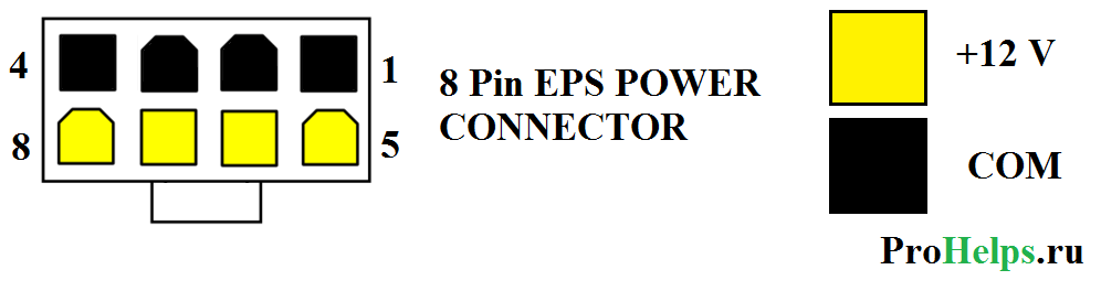
This cable was originally created for workstations to provide 12 volts of repeated power. But since many times have passed many processors require more nutrition and 8-pin cable is often used instead of a 4-pin 12 volt cable. It is often referred to as "EPѕ12V" cable.
4 + 4 pin EPS +12 volt power connector

 Motherboards can be with a 4-pin connector or a 8-pin 12 volt connector. Many food sources are equipped with 4 + 4-pin 12 volts cable, which is compatible with 4 and 8 continent contacts. A 4 + 4 Power cable has two separate pins 4 pieces. If you connect them together, 4 + 4 power cable, then you will have an 8-pin power cable that can be connected to an 8-pin connector. If you leave two parts separately, then you can connect one of the plugs of the 4-pin Motherboard connector.
6-pin PCI Express (PCIE) power cable connector

This cable is used to provide additional 12 volts for PCI Express Expansion Cards. This connector can provide up to 75 W PCI Express.
8-pin PCI Express (PCIE) power cable connector

PCI Express Specifications 2.0 released in January 2007 Added 8 pin PCI Express with power cable. It is just an 8-pin version of the 6-pin PCI Express with a power cable. Both are used mainly to provide additional video cards. The senior 6-pin version officially provides no more than 75 W (although it is unofficially, as a rule, can give much more), and the new 8-pin option provides a maximum of 150 W.
6 + 2 (8) PIN PCI Express (PCIE) power cable connector

Some graphics cards have a 6-pin PCI Express with power connectors and other 8-pin PCI Express connectors. Many power supplies are supplied with 6 + 2 PCI express power cable, which is compatible with both types of video cards. In 6 + 2 PCI Express, the power cable consists of two parts: 6-pin, and 2-plug. If you fold together these two parts, then you will have a full-fledged 8-pin PCI-Express connector. But if you split the connector into two parts, then you can only connect 6-pin.
CPU power connectors
CPU power comes from a device called Voltage Regulator Module (VRM), which is available in most motherboards. This device provides power to the processor (as a rule, through contacts on the processor socket) and produces self-calibration to suppress proper voltage to the processor. The design of the VRM module allows it to be powered by both from the incoming voltage +5 V and from voltage +12 V.
For many years, only +5 B is used, but since 2000, most VRM moved to +12 in due to lower requirements for working with such a voltage at the input. In addition, other components of the PC can also use a voltage of +5 V, which comes through a common contact on the nest of the motherboard, while only disk drives (in any case, it was up to 2000). Does VRM use on your board voltage +5 V or +12 B depends on the specific model board and the stress controller design. Many modern VRM are arranged in such a way as to receive at the voltage input from +4 V to +26 V, so the final configuration determines the manufacturer of the motherboard.
For example, someone in our hands got a FIC motherboard (First International Computer) SD-11, equipped with a regulator of SEMTECH SC114ABCSW voltage. This fee uses the +5 V voltage, converting it to lower in accordance with the needs of the CPU. Most motherboards use VRM two manufacturers - Semtech or Linear Technology. You can visit the sites of these companies and study the specifications of their chips in more detail.
The motherboard, which is spent on, used the Athlon processor 1 GHz Model 2 in the version with a slotted slot (Slot A) and according to the specification, required 65 W, at a nominal voltage of 1.8 V. 65 W at a voltage of 1.8 B corresponded to the current 36 , 1 A. When using VRM with an incoming voltage +5 in power 65 W corresponds to the current of total 13 A. But this alignment is obtained only under the condition of 100% of the voltage controller, which is impossible. Usually, the effectiveness of VRM is about 80%, thus, to ensure the operation of the processor, together with the voltage regulator, the current will be approximately equal to 16.25 A.
If we consider that other energy consumers on the motherboard are also used by the line +5 V - remember that the ISA or PCI cards also use this voltage - you can make sure how easy it is possible to overload the +5 in the power supply.
Although most of the VRM design solutions on motherboards are inherited from Pentium III and Athlon / Duron processors using +5 B regulators, most modern systems are used by VRM, designed to voltage +12 V. This is due to the fact that higher voltages reduce the current level. We can make sure that the example of AMD Athlon 1 GHz, about which already mentioned above:
| Current level depending on the incoming voltage | |||
| Power | Voltage | Tok Power | Current strength in Ampere taking into account the efficiency of the voltage regulator 80% |
| 65 W. | 1.8 B. | 36.1 A. | - |
| 65 W. | 3.3 B. | 19.7 A. | 24.6 A. |
| 65 W. | 5.0 B. | 13.0 A. | 16.3 A. |
| 65 W. | 12.0 B. | 5.4 A. | 6.8 A. |
As you can see, the use of the +12 in to power the chip requires a current of the force of only 5.4 or or 6.8 A, taking into account the effectiveness of VRM.
Thus, by connecting the VRM module on the motherboard to the power line +12 V, we could extract a lot of benefit. But, as you already know, the ATX 2.03 specification assumes only one +12 V line, which is transmitted through the main motherboard power cable. Even who lived a brief life, the auxiliary 6-pin connector was devoid of contact with the tension +12 V, so he could not help us. The current by force is more than 8 A by one wire of the 18th caliber from the line +12 in the power supply is a very effective way to melt the contacts of the ATX connector, which according to the specifications are designed for current not higher than 6 A when using standard Molex contacts. Thus, a fundamentally different solution was required.
Platform Compatibility Guide (PCG)
The processor directly controls the power of the current passing through the contact +12 V. Modern motherboards are designed to provide support for as many processors as possible, however, VRM circuits some boards may not provide sufficient food for all processors that can be installed in socket on the motherboard. To eliminate potential compatibility issues that can lead to an unstable PC work or even failure of individual components, Intel has developed a power standard called Platform Compatibility Guide (PCG). PCG is mentioned on most intel boxing processors and motherboards manufactured from 2004 to 2009. It was created for PC and system integrators to convey to them information about which requirements makes a power processor, as well as the motherboard compliance with these requirements.
PCG is a double-digit or three-digit designation (for example, 05a), where the first two digits mean the year when the product was presented, and the additional third letter corresponds to the market segment. PCG marking, including the third mark A, correspond to processors and motherboards related to low-end solutions (require less energy), while the letter B refers to processors and motherboards relating to the high-end market segment (require more energy ).
Motherboards that support High-End Class processors, by default, can also work with less productive processors, but not vice versa. For example, you can set the processor with PCG marking 05A in the motherboard having a 05B marking, but if you try to install the 05B processor in a fee having a 05A marking, you may easily encounter unstable operation of the system or other, more severe consequences. In other words, there is always the opportunity to establish a less productive processor in an expensive motherboard, but not vice versa.
| Recommendations for the power level along the line +12 V in accordance with the Intel Platform Compatibility GUIDE (PCG) labeling | |||||
| PCG code | Year | Market segment | CPU energy consumption | Permanent current over the line +12 in | Peak power over the line +12 in |
| 04A. | 2004 | Low-End. | 84 W. | 13 A. | 16.5 A. |
| 04b. | 2004 | High-End. | 115 W. | 13 A. | 16.5 A. |
| 05A. | 2005 | Low-End. | 95 W. | 13 A. | 16.5 A. |
| 05b. | 2005 | High-End. | 130 W. | 16 A. | 19 A. |
| 06 | 2006 | Everything | 65 W. | 8 A. | 13 A. |
| 08 | 2008 | High-End. | 130 W. | 16 A. | 19 A. |
| 09A | 2009 | Low-End. | 65 W. | 8 A. | 13 A. |
| 09B. | 2009 | High-End. | 95 W. | 13 A. | 16.5 A. |
The power supply must be able to withstand the peak load at least for 10 ms.
The power supply that corresponds to the required minimum on the +12 V line can provide stable operation of the system.
4-pin CPU power connector +12 V
To increase the current over the +12 V line, Intel has created a new ATX12V BP Specification. This led to the appearance of the third power connector, which was called ATX +12 V and was used to sum up the additional voltage +12 V to the motherboard. This 4-pin power connector is standard for all motherboards corresponding to ATX12V specifications, and contains contacts Molex Mini-Fit Jr. With forks such as "Mom". According to the specification, the connector complies with the standard Molex 39-01-2040, the type of the context - Molex 5556. This is the same type of contacts that is used mainly to power the ATX motherboard.
This connector has two contacts +12 V, each of which is designed for current to 8 A (or up to 11 A when using HCS contacts). This ensures the strength of the current 16 and in addition to the contact on the motherboard, and in the amount both connectors provide a current to 22 A along line +12 V. The location of the contacts of this connector is shown in the following scheme:
Connector +12 in processor power, frontal view and layout of contacts
Appointment of contacts on the +12 connector B is presented in the following table:
| 4-pin connector +12 B to power CPU | |||||
| Contact | Signal | Color | Contact | Signal | Color |
| 3 | +12 V. | Yellow | 1 | GND. | The black |
| 4 | +12 V. | Yellow | 2 | GND. | The black |
Using standard Molex contacts, each contact in the +12 B connector can be carried out with a strength of up to 8 A, 11 A with HCS contacts, or up to 12 A with Plus HCS contacts. Even though in this connectivity, the same contacts are used as mainly the current on this connector can reach higher values, since fewer contacts are used. By multiplying the number of contacts for the voltage, you can determine the limit power of the current according to this connector:
Standard Molex contacts are designed for current 8 A.
Contacts Molex HCS designed for current 11 A.
Contacts Molex Plus HCS Detached 12 A.
All values \u200b\u200bare indicated for a bunch of 4-6 contacts Mini-Fit Jr. When using wires of the 18th caliber and standard temperature.
Thus, in the case of using standard contacts, power can reach 192 W, which, in most cases, is sufficient even for modern productive CPUs. Consumption of greater power can lead to overheating and placing contacts, so in the case of the use of more "voracious" models of processors fork +12 B to power the processor should include Molex HCS contacts or Plus HCS.
The 20-pin main power connector and the processor power connector +12 into together provide the maximum current power level of 443 W (when using standard contacts). It is important to note that adding the connector +12 in allows you to use the full power of the power supply of 500 W, without risking to encounter overheating or melting contacts.
Adapter on the +12 connector in processor power
If a power Supply It does not have a standard connector +12 B to power the processor, and on the motherboard there is a corresponding socket, there is a simple way out of the problem - use the adapter. What nuances can we face in this case?
The adapter connects to the connector for peripheral devices, which is available in almost all of the BP. The problem in this case is that the connector for peripheral devices is only one contact +12 V, and the 4-pin CPU power connector is two such contacts. Thus, if the adapter assumes the use of only one connector for peripheral devices using it to ensure the voltage immediately on two contacts of the connector +12 B for the processor, then in this case we see a serious inconsistency between current requirements. Since the contacts on the peripheral devices are calculated on the current only at 11 A, the load exceeding this value can lead to overheating and placing contacts on this connectivity. But 11 A is below the peak current values \u200b\u200bto which the contacts should be calculated in accordance with the Intel PCG recommendations. This means that such adapters do not comply with the latest standards.
We made the following calculations: Given the effectiveness of VRM at the level of 80%, for the average of the processor consuming 105 W, the current level will be approximately 11 A, which is maxima for the peripheral power connector. Many modern processors have TDP over 105 W. But we would not recommend using adapters that use only one connector for peripheral devices, with processors having a TDP above 75 W. An example of such an adapter is shown in the following figure:

Adapter on the power connector CPU +12 V with connector for powering peripheral devices
8-pin CPU power connector +12 V
In the High-End Class Motherboards, several VRMs are often used to power the processor. To distribute the load between the additional voltage regulators, such boards are equipped with two sockets for the 4-pin connector +12 V, but physically they are combined into one 8-pin connector, as shown in the figure below. This type of connectivity was first presented in the EPS12V version 1.6 specification, released in 2000. Although initially this specification was focused on file-servers, the increased power requests for some high-performance processors for desktop PCs led to the fact that this 8-pin connector appeared in the PC world.

8-pin CPU power connector +12 V. Front view and contact configuration
Purpose of contacts of the 8-PIN CPU connector +12 B is provided in the following table:
| 8-pin CPU +12 power connector in | |||||
| Color | Signal | Contact | Contact | Signal | Color |
| Yellow | +12 V. | 5 | 1 | GND. | The black |
| Yellow | +12 V. | 6 | 2 | GND. | The black |
| Yellow | +12 V. | 7 | 3 | GND. | The black |
| Yellow | +12 V. | 8 | 4 | GND. | The black |
Some motherboards where 8-pin CPU power connector is used to ensure correct operation should receive voltage to all connectivity contacts, while most of the motherboards of this type can work, even if you use only one 4-pin power connector. In the latter case, four free contact will remain on the nest of the motherboard. But before running a computer with such a configuration of connectors, you need to read the manual of the motherboard user - most likely, it will be reflected, it is possible to connect one 4-pin power connector to the 8-housing socket on the board, or not. If you are using a processor that consumes more energy than one 4-pin power connector can provide, however, you will have to find a BP equipped with an 8-pin connector.