Arduino control the robot using bluetooth. A car with proportional control via Bluetooth from Android. Working with Android application
The cordless screwdriver is an excellent household helper. The tool, together with the master, works in the house and in the garden, works in the garage or in the field. Until the battery runs out. The number of charge-discharge cycles of the battery is limited, the battery also deteriorates from idleness: self-discharge destroys the cells. On average, the battery lasts 3 years, after which it has to be replaced. You can save the tool by converting it into a network one. The rework is done in different ways.
Is it really worth the remodel?
Without batteries, the screwdriver turns into a piece of iron. When the batteries no longer hold a charge, you have to look for new batteries. Firstly, it is expensive - the price of batteries is up to 80% of the cost of a screwdriver, it is more efficient to buy a new tool. Secondly, batteries are not always on sale, for example, if a model is discontinued. Thirdly, the zealous owner seeks to use every opportunity to save money.
Converting a cordless screwdriver to work from electrical network - good way out... What does it give:
- The instrument gets a new life.
- No more batteries needing to be charged.
- The tool torque is independent of the battery charge.
The disadvantage of the redesigned design is the dependence on the socket and the length of the network cable.
Attention! Work at a height exceeding two meters is not allowed with a converted screwdriver.
How to convert a cordless screwdriver to operate on a 220 volt network
The craftsmen came up with several ways to remake the screwdriver to work on the electrical network. All of them are to provide the motor with the required supply voltage using an intermediate source or converter.
Table: Power supply options for the mains screwdriver
| Power supply | Dignity | disadvantages |
| Complete charger for screwdriver. |
| The charger takes up space on the table. |
| A ready-made power supply placed in an old battery case. |
|
|
| Homemade power supply, placed in an old battery case. |
|
|
| External power supply | Easy rework. |
|
| Computer power supply |
|
|
Connecting the screwdriver to the charger
Attention! At low voltage, there are great losses in the wire, so the cable between the charger and the tool should be no longer than 1 meter, with a cross section of at least 2.5 square meters. mm.
Sequencing:
- Disassemble the old battery and remove the dead cells from it.
- Drill a hole for the cable in the battery case, thread the cable through the hole. It is advisable to seal the connection with electrical tape or heat shrink tubing so that the wire does not break out of the housing.
- The elements removed from the battery will disrupt the weight distribution of the screwdriver - the hand will get tired. To restore balance, a weight should be placed in the hull - it can be solid wood or a piece of rubber.
- Solder the cable to the terminals former battery connected to the screwdriver.
- Assemble the battery case.
- It remains to test the updated tool at work.
Solder or attach two wires to the terminals of the charger with crocodile clips.
Mounting the finished power supply in the old battery case
Attention! In a closed case, the power supply does not cool well. It is recommended to make holes in the walls of the enclosure. Do not use the tool continuously for more than 15 minutes.
Procedure:
- Disassemble the old battery and remove the non-working cells from it.
- Install the power supply into the battery case. Connect high voltage contacts and low voltage terminals.
- Assemble and close the battery case.
- Insert the battery into the screwdriver.
- Plug the power supply into a power outlet and test the updated mains tool in operation.
Homemade power supply
Attention! Observe electrical safety rules. Solder and connect with the device de-energized.
Step-by-step instruction:
- Disassemble the case of the old battery, remove the dead batteries from it.
- Install the elements of the electrical circuit of the power supply on the circuit board, solder the contacts.
- Install the assembled board into the case. Check the presence of voltage at the output with a tester.
Power supply in the case
- Connect the low voltage wires to the terminals of the old battery. Assemble the case.
All that remains is to assemble the battery case
Connect the screwdriver to the electrical network and check its operation.
Video: homemade lithium battery for a screwdriver
Connecting to an external power supply
Attention! In the process of revision, you will need to disassemble the screwdriver body and interfere with the electrical circuit. Memorize the disassembly sequence to reassemble all parts in reverse order.
What to do:

Connecting to the power supply from a computer
Instructions:
- Find or buy a power supply unit from a computer with a capacity of at least 300 watts.
- Disassemble the screwdriver body. Find the inside of the motor power wires. Solder the connectors to the wires for computer unit nutrition.
- Remove the connectors for connecting the computer power supply from the case.
- Connect the screwdriver to the new power supply.
- Connect the power supply to the mains and check the operation of the device.
Video: power supply for a screwdriver from a computer PSU
How to power a screwdriver while maintaining its autonomy
If the master works in a building to which no electricity is supplied, and the batteries have already deteriorated, there are ways to power the screwdriver:
- replace old battery banks with new ones;
- connect the screwdriver to the car battery;
- connect the tool to a different battery, such as from an uninterruptible power supply.
Replacing old elements
Attention! When replacing batteries, pay attention to the correct polarity of connecting the cells.
Procedure:

Attention! Charge a converted battery only with a specially selected charger.
Connecting to an external battery
Sequencing:
- Buy or find external battery, for example, take from an unnecessary uninterruptible power supply.
- Take a wire with a cross section of at least 2.5 sq. mm. Remove the insulation and fit the clamping terminals on the copper ends suitable for attaching to the battery.
- Place the other end of the cable in the case of the old battery and solder to the terminals inserted into the screwdriver.
- Insert the battery case into the screwdriver, connect the cable with the terminals to the battery.
- Try the remanufactured tool in operation.
An electric cordless tool lasts several times longer than the batteries that supply it. Throwing a screwdriver with unusable elements in the trash is unreasonable. The real owner will be able to repair the device by transferring it to another power source, thereby giving it a new life.
When the batteries stop working, many are wondering how you can convert a cordless screwdriver into a network one. It is impossible to repair batteries with damaged cells. The cost of new power supplies is almost equal to the price of a screwdriver. It is not always possible to find suitable elements; models are often taken out of production. But for zealous and skillful owners there is a way out - to power the screwdriver from the mains.
Power supply for the screwdriver - 2 main options
There is only one drawback of the converted instrument: it is tied to an outlet. But for indoor work this is not so essential. But there are more advantages. Now you don't have to worry about recharging the battery, there will be no downtime. The current strength remains stable all the time and does not depend on the discharge of the battery, which means the constancy of the torque.
Before you go in search of a power supply unit (hereinafter referred to as a power supply unit), study the parameters of the screwdriver, which are indicated on the case or in the passport. Pay attention to the voltage. A 12-volt instrument is more common; it is not difficult to find a power supply for it. If the tension is greater, the search may be delayed. It is required to find out the consumed current, which is not indicated in the technical specification. The unit being purchased must provide an average current value (between the battery capacity and the standard charger). The data can be found from the marking.
There are two main options for converting a 220 volt cordless screwdriver. The first is to use an external power supply unit. Any rectifier capable of supplying the required constant voltage will do. Even if it is large and bulky, there is no problem. After all, you don't have to carry it around the room. The unit is installed near the outlet, and the cord to the tool is made of the required length.

Remember that with decreasing voltage, the amperage rises if the power remains the same. This means that the cross-section of the low-voltage cord must be larger than that from a 220 V network.
The second option is that the PSU is mounted in a battery case. The only obstacle in choosing this method may be the size of the transformer. Mobility is maintained, the radius of use depends on the length of the power cord. It is important to remember that the instrument is supplied with 220 V power, so the cord must be reliable, and the entrance itself is made neatly, carefully insulated.
Which external units can be used - an old computer or a laptop charger?
Available power supplies can be used as an external source:
- charger for car batteries;
- PSU from an old computer;
- charging from a laptop;
- homemade power supply unit.

You can buy an old charger on the market inexpensively. Pulse chargers are now mainly used, and old devices are often sold as unnecessary. It is such a charger with the ability to manually adjust the voltage and current that is ideal for any screwdriver, regardless of its operating voltage. The whole alteration consists in connecting the low-voltage cord to the output contacts of the charger.
The computer power supply is purchased from older models and must have a shutdown button. You will not need it, but this is exactly the version of the AT format that you need. On the radio market, a block with a capacity of 300-350 watts is selected, which will ensure reliable operation of low-power and medium-sized screwdrivers. Everything specifications are indicated in a sticker on the body. The unit has a cooling fan and overload protection. To convert a computer power supply unit with our own hands to an external one for a screwdriver, we perform simple operations:
- disassemble the case;
- on the large square connector we find the green wire and any black one;
- we connect both wires to each other, insulate;
- on the other smaller connector, remove all the wires, leaving yellow and black;
- we solder the cable cord to them.
To observe the polarity, you should know: yellow wire - positive, black - negative ... An instrument with a voltage of up to 14 volts works from a computer power supply.
Majority chargers from a laptop have characteristics that allow them to be used as a power source for a screwdriver. Chargers with an output voltage of 12-19 volts are suitable. The only changes that need to be made are related to the output plug. Cut it off, strip the wires and solder a cable of the required length to them.
Individuals with an understanding of electrical engineering can make a homemade power supply. Its circuit is quite simple and includes a step-down transformer, a diode rectifier and two capacitors. All parts can be bought or taken from old radio equipment. A transformer from a tube TV with an output of 24-30 V. A rectifying diode bridge is required. Capacitors are used not in short supply, from old technology: one for 0.1 microfarads and the other electrolytic for 4700 microfarads.

Attention! The structure must be enclosed in a housing. To protect against short circuits, it is mandatory to install fuses at the input and output.
How to place a PSU in a case - 3 different possibilities
The mains can be placed in the battery case or in the handle. Possible options:
- any PSU suitable in terms of characteristics and size;
- Chinese power supply unit for 24 V;
- homemade.
On the radio market, a power supply unit with the necessary parameters is selected. At home, it should be carefully removed from the case and placed in your screwdriver, all components securely fastened. If the wires are short, lengthen them so that they do not touch metal parts. Place the transformer and the board separately. Install additional heatsinks on microcircuits for better cooling. Also, holes in the case will not be superfluous so that air circulates and heat is removed during operation.

In a radio parts store, we buy a power supply unit for 24 V, current 9 A. Screwdrivers operate from 12 or 18 Volts, so the task is to lower the voltage to the required level. To do this kind of work, a minimum knowledge of radio engineering is required. The output voltage is maintained by a 2320 ohm resistor R10. A 10 kΩ trimmer should be installed instead. How to configure the power supply is described below:
- solder the permanent resistor;
- set the resistance of the trimmer resistor to 2300 Ohm for the device;
- the trimmer resistor is soldered in place of the constant;
- when the power supply unit is on, adjust the voltage.
The design of a homemade power supply unit will be based on electronic transformer Feron or Taschibra at 60 watts. These can be purchased at an electrical store and are designed for halogen lamps. They do not require any alteration. Tapping the secondary winding from the midpoint made it possible to use two Schottky diodes instead of the usual four. The operation of the power supply unit is monitored by the HL1 LED. The diagram shows all the necessary details.

The T1 transformer is wound independently. A non-deficient ferrite ring НМ2000 with a size of 28 × 16 × 9 is used. Before winding with a file, the corners are cleaned, the ring is wrapped with FUM tape. The block made is mounted on an aluminum plate with a thickness of 3 mm or more, placed in the battery case. It also serves as a common wire.
How to Install Correctly - Do you need a counterweight?
Reliability in operation and safety depend on the reliability of the installation of the electrical part. A soft stranded cable is used as a mains and low-voltage cable. If the device is external, connect the ends of the cable to its terminals. We treat copper wiring and brass contacts with soldering acid, after which they are easily soldered. In practice, special clips are often used - "crocodiles". In the screwdriver itself, soldering is indispensable, the "crocodiles" do not hold so tightly that the contacts do not disconnect during operation.

Ideally, use an old battery case. It is disassembled and the entire interior is removed. In this case, harmful substances are released, care should be taken to protect the respiratory tract and skin. The body is washed with a soda solution, running water and dried. From the inside of the contacts, we solder the ends of the cable, observing the polarity. In order not to guess, we temporarily connect the cable, turn on the screwdriver and look in which direction the spindle rotates, mark the wires. We make a hole in the lower part of the case, we pass the wires. Inside the case, the cord should be securely fixed by wrapping insulating tape around it. This thickening will prevent the wiring from pulling and breaking. Then we solder the ends to the contacts.
We place a counterweight inside the body. The best material there will be extruded rubber. It has the necessary characteristics: high density, insulating properties. To prevent the rubber from dangling inside, we cut it out with a slight overlap. To place the counterweight in the body, bend the material slightly and place it so that it does not vibrate and serves as additional insulation. Perhaps some counterbalance will seem superfluous, but it is not. The design of the screwdriver provides that the center of gravity is in the handle. This puts stress on the hand, but relieves the hand. When the batteries are removed from the body, the center of gravity shifts, increasing the load on the hand. It becomes uncomfortable and difficult to work. The homemade counterweight restores the center of gravity close to the factory one.
How to use a cordless screwdriver - simple rules
You have seen how easy it is to convert a cordless screwdriver to a cordless one. The practice of craftsmen suggested simple and useful tips for operation:
- after 20 minutes of work, you should give the screwdriver a five-minute rest;
- fix the electric cable on your hand so that it does not interfere with work;
- the power supply unit should be regularly cleaned from dust;
- do not use extension cords to connect the power supply to the network;
- The power supply unit must be grounded;
- Do not use power screwdrivers at work at height.
Compliance with these rules will extend the life of the updated instrument. Mobility is a little lost, but the unit does not require recharging, it works smoothly and confidently.
In this article, we will consider connecting and controlling the Arduino via bluetooth.
The widespread hc-06 will be used as a bluetooth module.
In our project, we will turn on and off the LED connected to port 13 via bluetooth.
Let's start by writing an application for an android smartphone. The application will be written in a convenient and simple App Inventor programming environment. Programs will be compiled online.
Follow the link http://ai2.appinventor.mit.edu/. There you will be asked to sign in to a Google account, which you will have to create if you don't already have one.
After entering you will be taken to the program, where you can create a project by clicking "start new project". You will need to enter a name for the project. Let's call it led_control.
Will open empty window applications.

Here we will have necessary components... Select the ListPicker in the window on the left and drop it into the project.

Find the Text property of the ListPicker component in the window on the right, and change "Text for ListPicker1" to "Select BT device".
Open the Layout tab in the window on the left, place the HorizontalArrangement component in the application, change its Width property to "Fill parent". Add 2 Buttons to the HorizontalArrangement, for each of them set the Width property to "Fill parent". It should look like this:

Let's change the labels on the buttons: the first one will say LED ON, the second - LED OFF.

Below we add a Label and clear its Text.
It remains to add a component that organizes data transmission via bluetooth. Open the Connectivity tab and place the BluetoothClient in the project. This component will not appear on the phone screen, but under it, because it is not visual.

Now you can start writing the program. In the upper right part of the program, select the Blocks mode.
Here the program will be compiled from graphic blocks. Click on the ListPicker1 component on the left and select ListPicker1.BeforePicking.

Click on ListPicker1 again and select set ListPicker1.Elements to


Place it like in the screenshot.
This gives us a list of paired bluetooth devices. Now let's connect to the selected device. Write a block like in the screenshot below.

The pink block labeled Connected is the first block in the Text tab. Enter Connected in the empty box.
Now let's write a button handler. Pressing the first button will send the text "led_on", and pressing the second will send the text "led_off". The label in Label1 will also change.

It remains to download the project to your smartphone. Click Build and choose a download method.

For the first option, you will need the Internet and a QR code reader. Click and wait until the project is completed and the QR code is generated, then open the QR code reader on your smartphone and read the code. All that remains is to download and install the file.
In the second version, the project in .apk format will be saved to your computer and you can upload it to your smartphone by any in a convenient way(for example via USB).
Now let's start with the Arduino program.
Data transmission and reception is carried out through the COM port, so we will use Serial. We will receive signals character by character, form a string, and then compare the generated string with the led_on and led_off commands.
Arduino
String val = ""; void setup () (Serial.begin (9600); pinMode (13, OUTPUT);) void loop () (while (Serial.available ()) (// while data arrives char c = Serial.read (); // read them val + = c; // and form the line delay (3);) if (val! = "") (Serial.println (val);) if (val == "led_on") (digitalWrite (13, HIGH );) else if (val == "led_off") (digitalWrite (13, LOW);) val = "";)
String val = ""; void setup () ( Serial. begin (9600); pinMode (13, OUTPUT); void loop () ( while (Serial. available ()) ( // while data arrives char c = Serial. read (); // read them val + = c; // and form a string delay (3); } |
Upload the code to Arduino.
Now you can connect the HC-06 Bluetooth module. It is connected very simply:
Vcc 5v (3.3v can)
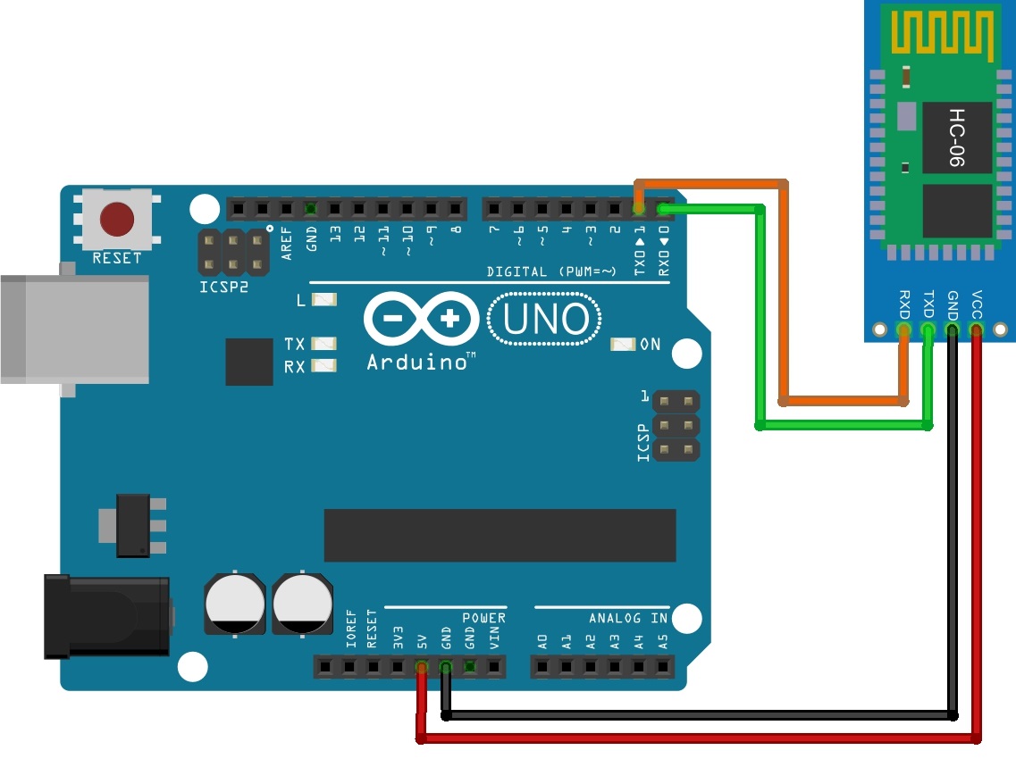
IF YOU TRY TO DOWNLOAD THE APPLICATION IN ARDUINO WITH A CONNECTED MODULE, AN ERROR WILL LEAVE, BECAUSE AND THE MODULE AND THE SOFTWARE LOADING WILL AFFECT THE RX AND TX PORTS!
Power up the Arduino. The LED on the bluetooth module should blink, which means that it is waiting for a connection. Take your smartphone, search in bluetooth settings, turn it on and start search. Find the device named hc-06 and connect to it. It may not work the first time. After one successful pairing, you can launch the program on your smartphone.
First, click on "Select BT device" and select the module from the paired devices. Then press the LED on and off buttons. If everything is done correctly, then everything will work.
We made a very simple application with using bluetooth, without design and even checking whether we are connected to the module or not. In the next lessons, we will make more complex applications and get a better understanding of App Inventor.
Arduino and Bluetooth machine without code editing. We will use specialized free sketching software. In addition, you do not need to buy a chassis for our craft, almost any faulty radio-controlled model of a car or tank will do.
I suggest watching an overview video about a bluetooth-controlled machine and its filling.
So, let's take a look at a live example of how to make your own hands remotely controlled via bluetooth c android tablet or smartphone typewriter. The article, oddly enough, is designed for the initial level of knowledge. There is no tutorial on how to edit code in the Arduino IDE here, and we will only use it to fill in our code. And we will compose a control algorithm in a program called FLProg. Smartphone control program - HmiKaskada_free. But first, about the hardware that we need.
Arduino machine and Bluetooth - hardware.
The first thing you need is chassis, that is, a body with wheels and motors, which will ride for the joy of us and those around us. In my case, the body was used from a radio-controlled toy in which the power section burned out. The prospect of renovation seemed to me dull, and I wanted something new for my children. This is how this project was born. There are two engines in the hull that drive the wheels along the sides of the car, like a tank. All electronic filling went to spare parts.
To control the electric motors of our future creation, you will need H-bridge on the L298N microcircuit Link to Ali, I took from this one. The picture is clickable.
H-bridge for arduino
It can drive two motors in the voltage range of 5 - 35 volts. Supports PWM, that is, you can adjust the speed of the motors. The board has a stabilized voltage output of 5 volts to power the arduino.
The connection diagram is simple and straightforward:

The next integral part of the electronic filling of our project is bluetooth module HC-06. The most common module for arduino, so popular that it does not need an additional description.

HC-06 bluetooth for arduino
The main element and the brain in my case is arduino nano, here I will not even upload a photo, because everyone knows about her and know how to work with her. By the way, any Arduino board is suitable, as long as it fits into the case 😀
Batteries and wires for soldering do not need specification definition. The choice of batteries depends on the operating voltage of the electric motors.
Arduino and Bluetooth car - sketching.
I will repeat myself - there will be no digging in the code here. We will use popular program FLProg. Download it latest version can be found on the official website. The program interface is simple and unpretentious, but there is a huge functionality and support for almost all popular modules. I will not write how to use it, as it will take a couple of articles. I will just say that I have not come across a more convenient and accessible program for drawing up sketches for arduino and its clones. Interface screen:

FLProg interface
The site is full of text and video manuals, I think you can figure it out.
My project for a remotely controlled machine can be downloaded from a Yandex disk.
Arduino machine and Bluetooth - control interface on the android tablet.
By popular demand I wrote detailed instructions on the development of a control interface based on HmiKaskada android in the article. The link is clickable.
For devices under android control there is a program HmiKaskada (link to YandexDisk). It was originally designed as an alternative to expensive industrial HMI panels. But inquisitive minds quickly realized that she could control anything. In our case, a typewriter. Supports wireless interfaces Wi-Fi and Bluetooth, in addition, you can connect the device directly via USB.
There are paid and free versions of the program. I have both but I basically made the project in free version to show you and once again make sure that the free version is absolutely working. The main difference between free and PRO versions is that it only works on bluetooth.
There is a giant thread on the FLProg forum regarding Cascade compatibility, and the developer is active and outgoing. I see no point in uploading the screen of the control panel - it is in the video.
We will not buy bad toys from the Chinese, but we will buy from them a cheap construction-chassis, a few modules and put our hands on it!
Here's what I got in the end: passable chassis, controlled - TA-DA !!! - from my Android smartphone.
“I am straight, I am sideways,
With a turn, and with a jump,
And with a run, and on the spot,
And two feet together ... "
Today we will put together a fun car with Bluetooth remote control. Source codes of the control program for Android included.
Decent toy specimen
I have two children, a daughter and a son. Both are given toys for their birthdays. As a rule, what is given to my daughter does not cause my negative reactions. And the son, as expected, is given all kinds of cars, tanks and other equipment. Of all this breakthrough of Chinese, I have no complaints only about the toy chainsaw, which I myself gave.Why is that? Probably because this saw was sold at the STIHL tool shop. I believe STIHL has made a toy analogue of its products in a small advertising run. As a result, a completely sane toy was born, very similar to its older brother. The rubber chain is spinning, 80 percent of the controls are implemented. There is even a cord with a handle for winding the saw, a switch, a gas button. The kit includes a spare chain and a tool for changing the chain.
Here's a toy saw
What am I talking about? Oh yes, about architecture! This I mean, if you want, you can make an excellent toy. And there is something to be equal to.
We will build a car with remote control!
Radio-controlled toys are of practical and technical interest. However, a child aged 4-6 will not be gifted with "Adult" Proportional Control toys. Most likely, the toy will be broken and the money wasted.As a result, they usually give something inexpensive. Of all this - "inexpensive" - cars or very fast or braking; the tanks are weak; and other obvious and hidden flaws. And of course no proportional control.
One fine day, the right wheel of one of the cars stopped turning. Dismantled, checked the motor - serviceable.
There are three microcircuits on the control board - China is crazy, I could not find sane documentation. One chip - a radio signal receiver with logic outputs and two bridge motor drivers. One of the drivers is out of order. I did not succeed in piling a bridge motor driver from discrete components right away.
There was nothing suitable in the local radio parts store. So I went to distant countries for the miracle microcircuits. I packed my belongings, stuffed my pockets with breadcrumbs, poured a cup of coffee, launched the browser and went ....
I found a motor driver suitable for the parameters, I ordered two at once. Just in case, suddenly one will be defective or I'll sleep myself. It was then that the thought of my typewriter began to emerge. After the package arrived from glorious China, I successfully replaced the driver and the machine was repaired.
Without putting on the back burner the idea of my car, I again leaned in to choose the basis - the chassis of the future car. Chassis are different for land transport: tracked, wheeled, with two, three, four wheels, etc.
How I chose the chassis
Firstly, I chose a land mode of transport, which means that I will have a chassis on land. Tracked chassis are generally more expensive and not too fast. Two-three-wheeled vehicles seem to me to be poorly passable, such a chassis can only ride on a flat surface.I settled on. In my opinion, such a chassis will have excellent cross-country ability and speed.

Chassis delivery set:
two acrylic plates with a bunch of technological holes for attaching all possible sensors, control boards and other components
4 wheels
4 complete actuators (electric motor + gearbox)
4 slotted discs for speed sensors, one for each wheel
fasteners
Yes, this is China again. Yes, cheap. Yes, very high quality. BUT! We should try first. After all, the "adult" chassis and stands in an adult way, we have not grown up to it yet.
Swamp of thoughts and Terms of Reference
When you hold a promising thing in your hands, for example, in terms of the possibilities for attaching the model with all kinds of sensors, servo, etc., you start to drown in a swamp of thoughts and a quagmire of prospects. But let's say to ourselves - STOP! And we will make ourselves a mini-TK for a prototype with brief description all nodes.We should have an RC model of a ground vehicle with control via Bluetooth, with the possibility of reversing and smooth regulation of the wheel speed.
What do we need to assemble the car?
.
There are no swivel wheels, which means that steering will be similar to that of a tracked vehicle. That is, for forward / reverse motion, the right and left side of the drives rotate at the same speed. And to make a turn, the rotation speed on one of the sides must be less or more.


For remote control we use the Bluetooth channel with a typewriter. The HC-06 module is a Bluetooth bridge, a serial interface that allows data transfer in both directions. At the input - TTL signals of the serial interface "RxD" and "TxD" for connection to the microcontroller (target board).
Will serve as a remote control cellular telephone with Android. Let's write our own program!


The driver is two-channel, for the left and right pair of wheels. The driver has logic inputs for changing the polarity of the output (direction of rotation) and a PWM input, it will be possible to control the rotation speed.

This board is selected because lying around in a drawer and perfectly suited to our purpose. There are discrete inputs / outputs, MC signals "RxD" and "TxD" are output, where "HC-06" will be connected.
Looking ahead, I will say that the Olymex MOD-IO product is a tough brute force. It will be perfectly possible to apply the usual one, which is the continuation of the story!
Total: chassis + control board + Bluetooth module + Android control program.
General connection diagram
Not a circuit in its pure form, but a connection diagram, since all the boards are already ready for us, and it remains to connect them together.
Scheme in Proteus

I will not describe what and where I connected it. Most likely you will have a different control board. I attach the sources, so you can edit the firmware. Well, if someone is unable to compile the firmware for their board, please contact - I will help as you have free time.
Microcontroller program
The MK program is able to receive commands via a serial interface from a Bluetooth module.And, in accordance with the commands, control the left and right pair of drives. Reverse and speed control work with PWM.
The code is sufficiently commented. I would like to dwell separately on my implementation of data exchange.
Data reception is implemented through a circular buffer. The thing is not new and there are many implementations.
I have moved the functions of the ring buffer into a separate library consisting of:
header file ring_buffer.h and the function implementation file ring_buffer.c
To use the library, you need to connect it to main.c
#include "ring_buffer.h"
Next, in the header file, you need to configure the library. To configure, you need to specify only four directives:
#define RX_PACKET_SIZE 7 // RxD packet size #define BUFFER_SIZE 16 // Receive buffer size. Must be twice as large as RX_PACKET_SIZE #define START_BYTE "s" // Start byte #define STOP_BYTE "e" // Stop byte
There is nothing more to customize.
Code Usage In main.c we configure the USART of the microcontroller.
Calling the USART configuration function
USART_Init (MYUBRR);
#define BAUD 9600 #define MYUBRR F_CPU / 16 / BAUD-1 void USART_Init (unsigned int ubrr) (/ * Set baud rate * / UBRRH = (unsigned char) (ubrr >> 8); UBRRL = (unsigned char) ubrr; / * Enable receiver and transmitter * / UCSRB = (1<< TXCIE) | (1 << RXCIE)| (1 << TXEN) | (1 << RXEN); /* Set frame format: 8data, 2stop bit */ UCSRC = (1 << URSEL) | (0 << USBS) | (3 << UCSZ0); }
Receiving a data packet
In the function of the interrupt handler for receiving a byte via USART, we just need to put the received byte in a circular buffer. We will parse the package later.ISR (USART_RXC_vect) (uint8_t Data = UDR; RB_push_char (Data); // Add the received byte to a circular buffer)
Yes, I have neglected all frame checks for now.
Now we just have to check our buffer from time to time. To do this, I initiated a timer in which I set the flag to allow checking the circular buffer
ISR (TIMER0_OVF_vect) (TCNT0 = 0x64; ReadRingBuffer = 1;)
In the main loop, add a condition for checking the flag.
if (ReadRingBuffer) (if (RB_read_buffer ((uint8_t *) & RxPacket) == 1) Reading the buffer (// Parse the packet, do something) ReadRingBuffer = 0;)
Function RB_read_buffer checks the circular buffer, if the packet size, start and stop bytes are in their places - the packet is considered valid, the function returns "1." As an argument, the function accepts a pointer where to add the received packet.
For greater reliability, the package can be supplied with a checksum, in one of my commercial projects I did so. That is, the checksum check is added to the check of the size, start / stop bytes. But let's do without it for now.
How do I parse the package
Now the fun part is how I parse the package. The packet can transmit data larger than a byte, signed data, floating point data.Let me explain using the example of a package for chassis management. In addition to the start and stop bytes, in my packet I need to transmit one command, and two PWM values, for the left and right sides of the drives. For the command, one byte is enough for me, and for each PWM value, I transmit int16- 16 bit signed type. That is, I am not passing the direction flag (byte / tag). To change direction, I transmit a positive or negative PWM value.
The receiving package is organized in my structure.
struct RxPacket (uint8_t StartByte; uint8_t Command; int16_t Left_PWM; int16_t Right_PWM; uint8_t StopByte;) RxPacket;
By calling the function RB_read_buffer ((uint8_t *) & RxPacket), as an argument, we pass a pointer to the structure of the receiving packet. That is, when a packet is accepted, everything will be put into its own shelves in the RxPacket structure. Then it remains to read this data from the structure like this:
lCmd = RxPacket.Command; lLPWM = RxPacket.Left_PWM; lRPWM = RxPacket.Right_PWM;
Data packet transmission
Although transfer is not yet used in my program, nevertheless, the transfer option is implemented. It is easier to transfer data. In the same way as for the receiving packet, let's create a structure:struct TxPacket (uint8_t StartByte; uint8_t Rc5System; uint8_t Rc5Command; uint8_t StopByte;) TxPacket;
Where, there is a start and stop byte and an information part. We have already initialized the USART receiver.
To initiate the transfer of a packet - call the function
void send_packet () (// Write start byte to register UDR UDR = START_BYTE;)
In this example, in this function, I write only the start byte to the UDR register. It seems to be a little, but in the same function you can implement package preparation or something else useful. And this, in my opinion, is more logical. It is logical in terms of self-documenting code. That is, if I am in the code, I simply write the value into the UDR register, this can be perceived as transferring only one byte, and by calling the self-speaking function send_packet ()- I'm talking about sending a data packet.
Further, when the USART transmitter has sent all the bytes from the UDR register, the transmission interrupt handler will be called.
ISR (USART_TXC_vect) (unsigned char * Pointer = (unsigned char *) & (TxPacket); static unsigned char TxIndex = 1; if (TxIndex< sizeof(TxPacket))
{
UDR = *(Pointer + TxIndex);
TxIndex++;
}
else TxIndex = 1;
}
In the handler, I declare a pointer variable and assign it the address of the TxPacket structure. Next, a static variable is declared - the index of the transmitted byte, which is assigned a value when declared 1 ... We start with one because we have already sent the first byte from the structure. In general, in the structure, you can do without the start byte, I still send it separately, but the declarations of this byte are left in the structure to understand how the packet looks like.
The condition if (TxIndex< sizeof(TxPacket))
проверяет, что индекс меньше чем размер пакета. Если условие верно, то записываем байт в регистр UDR: UDR = *(Pointer + TxIndex);
increment TxIndex. When the USART transmits the next byte, we will again get into the handler, but the next byte from the structure will be transferred and all bytes of the structure will be transferred this way. When TxIndex is greater than the size of the structure, the condition will not be true and we will get into else TxIndex = 1; Where TxIndex will be initialized, but nothing is written to the UDR register, so the handler will no longer be called until the next packet transfer is initiated. Thus, the transfer process is completely automatic, and even if we change the structure of the packet, the handler does not have to be rewritten.
As part of the description of the MK program, it remains to tell about the implementation of driver control. The driver is controlled by three signals: A1 (B1), A2 (B2) and PWMA (PWMB). A1 and A2 are for turning on / off the driver and for reversing the polarity of the output. A PWM signal from the MK is fed to the PWMA input - you can control the rotation speed. For the PWM signal, I used two hardware PWM timers 1.
#define _WGM13 0 #define _WGM12 1 #define _WGM11 0 #define _WGM10 1 // Timer 1 init TCCR1A = (1<< COM1A1) | (0 << COM1A0) | (1 << COM1B1) |
(0 << COM1B0) | (_WGM11 << WGM11) | (_WGM10 << WGM10);
TCCR1B = (0 << CS12) | (0 << CS11) | (1 << CS10) |
(_WGM13 << WGM13) | (_WGM12 << WGM12);
TCNT1 =0x0000;
OCR1A = 0;
OCR1B = 0;
The timer is 16-bit, but the PWM is initialized to 8 bits. And as you probably already noticed, in the receiving package I have two values for setting the PWM, for the left and right drives, respectively. Signed 16-bit variables.
I will explain why I did this.
At first, it came from the program for Android. The fact is that in Java there are no unsigned types and I have already stepped on this rake. And to transfer a number from 0 to 255, I would have to somehow twist. I decided to go the simpler way - I send a signed 16-bit number. At the same time, 16 bits of the signed type is from -32786 to 32768, that's enough for us.
Secondly, so in my opinion it is more transparent - the speed of rotation and direction is described by only one variable.
And thirdly, whatever one may say, for our purposes, less than three bytes will not fit. Let's sacrifice one more byte, but everything becomes clear, a positive PWM value is a forward rotation, a negative value is a reverse rotation.
To control the drives, I wrote the function drive (int leftPWM, int rightPWM);.
void drive (int leftPWM, int rightPWM) (// Move FORWARD left wheel if (leftPWM> 0) (ClearBit (A2_PORT, A2_PIN); SetBit (A1_PORT, A1_PIN);) // Move BACK left wheel if (leftPWM< 0){
ClearBit(A1_PORT, A1_PIN);
SetBit(A2_PORT, A2_PIN);
}
// Движение ВПЕРЁД правое колесо
if (rightPWM >0) (ClearBit (B2_PORT, B2_PIN); SetBit (B1_PORT, B1_PIN);) // Move BACK right wheel if (rightPWM< 0){
ClearBit(B1_PORT, B1_PIN);
SetBit(B2_PORT, B2_PIN);
}
// Остановка
if (leftPWM == 0){
ClearBit(A1_PORT, A1_PIN);
ClearBit(A2_PORT, A2_PIN);
}
// Остановка
if (rightPWM == 0){
ClearBit(B1_PORT, B1_PIN);
ClearBit(B2_PORT, B2_PIN);
}
set_PWM((uint8_t)(abs(leftPWM)), (uint8_t)(abs(rightPWM)));
}
According to the PWM value, signals A1 (B1), A2 (B2) are controlled and the PWM value is set by calling the function set_PWM (leftPWM, rightPWM).
Uff, fizzled out ...
To summarize: received the packet, disassembled, passed the PWM value to the function drive.
Android application for cars
No, I will not analyze in such detail as a program for MK. I'm still a beginner in software development for Android and I'm not ready to talk competently and deeply enough.The main function of the program- data transmission to the HC-06 module via Bluetooth. The program has an uncomplicated interface.

Above is a drop-down list of paired Bluetooth devices for selecting a module. At first this list was not there, but at the end of the work on the article I decided to do it humanly, because not everyone will be able to understand the source code.

Then the "Off" button enables / disables communication with the "HC-06". Below left to right: left channel PWM transmitted value, sensor type, right channel value. Below are two sliders for adjusting the sensitivity of speed and rotation.
The program implements two types of machine control. To switch the sensor type, touch the sensor name inscription: "Tilt" or "Shuffle".
1. Control the car by tilting the phone. The phone's zero position is horizontal. When the phone is tilted forward, the PWM value increases in proportion to the tilt, in the range from 0 to 255. When the phone is tilted back, the PWM value decreases in proportion to the tilt in the range from 0 to -255

To turn left or right - you need to tilt the phone forward or backward and, at the same time, left or right, respectively. Yes, as in a real car, until you give in to the gas, the turn is not carried out.
2. Touch control. My brand name for this kind of management is "shuffle".

Think of it as a touchpad. When you touch in a gray square, the PWM value increases / decreases depending on the place of touch, the further from the center downward or upward, the higher / lower the value.
There are no "niceties" and bells and whistles. That seems to be all.
A little tar on "skis"
There is a cant on my phone. Yeah, the ski phone is the LG G2 mini. On it, the Bluetooth connection is inadequate. The connection is established normally only if Bluetooth was turned on just before starting the application.I did this: when starting the application, I check if Bluetooth is on, if it is off, I make a request to turn it on. And when "minimizing", closing the application - forcibly turn off Bluetooth.
And one more thing, when changing the screen orientation, Bluetooth turns off and again a request for turning on is issued, you have to turn off the automatic switching of the screen rotation.
Summary
I believe I have achieved my goal! With little effort, I created an RC model with sane proportional control. Even an adult can play the car with enthusiasm, making turns on the spot, writing complex pirouettes, slowing down and accelerating if necessary.And it can be easily repaired if it breaks.
There is also a field for activity, there is room for growth. You can “screw on” the chassis, you can upgrade and improve the software for your phone.
And this will be continued!