Dynamic range compressed or standard. Mastering in the opposite direction: Is it possible to increase the dynamic range of compressed records? Modifications of Khafman codes
During the time when the researchers also proceeded to solve the problem of creating a speech interface for computers, it was often necessary to manufacture equipment independently, allowing you to enter audio information into the computer, as well as display it from the computer. Today, such devices may have unique historical interest, since modern computers can easily equip the input and output devices, such as sound adapters, microphones, headphones and sound columns.
We will not delve into the details of the internal device of these devices, but we will tell about how they work, and give some recommendations for the choice of sound computer devices to work with recognition systems and speech synthesis.
As we have already spoken in the previous chapter, the sound is nothing more than air oscillations, the frequency of which lies in the frequency range perceived by the person. In different people, the exact limits of the range of audible frequencies may vary, however, it is believed that sound oscillations lie in the range of 16-20,000 Hz.
The task of the microphone is to convert audio fluctuations into electrical oscillations, which can continue to be reinforced, filtered to remove interference and digitized to enter sound information into the computer.
According to the principle of operation, the most common microphones are divided into coal, electrodynamic, condenser and electret. Some of these these microphones require an external current source (for example, coal and condenser), others under the influence of sound oscillations are able to independently produce alternating electrical voltage (These are electrodynamic and electret microphones).
You can also split microphones for the purpose. There are studio microphones that can be kept in hand or secure on the stand, there are radio microphones that can be fixed on clothes, and so on.
There are also microphones designed specifically for computers. Such microphones are usually attached on the stand on the surface of the table. Computer microphones can be combined with headphones, as shown in Fig. 2-1.
Fig. 2-1. Headphones with microphone
How to choose from all the variety of microphones the one that is best suited for speech recognition systems?
In principle, you can experiment with any microphone you have, unless it can be connected to a computer audio adapter. However, the developers of speech recognition systems are recommended to acquire such a microphone, which at work will be at a permanent distance of the speaker's mouth.
If the distance between the microphone and mouth does not change, the average electrical signal coming from the microphone will also change too much. This will have a positive effect on the quality of the work of modern speech recognition systems.
What is the problem here?
A person is able to successfully recognize speech, the volume of which is changing in very wide limits. The human brain is able to filter the quiet speech from interference, such as the noise of cars passing down the street, foreign conversations and music.
As for the modern speech recognition systems, their abilities in this area leave much to be desired. If the microphone stands on the table, then when the head is rotated or changing the position of the body, the distance between the mouth and the microphone will change. This will lead to a change in the level of the microphone output signal, which in turn will worsen the reliability of speech recognition.
Therefore, when working with speech recognition systems, the best results will be achieved if you use the microphone attached to the headals, as shown in Fig. 2-1. When using such a microphone, the distance between the mouth and the microphone will be permanent.
We also pay your attention that all experiments with speech recognition systems are best done, retaining in a quiet room. In this case, the effect of interference will be minimal. Of course, if you need to choose a speech recognition system capable of working in conditions of strong interference, the tests need to be carried out differently. However, as far as it is known to the authors of the book, while the observance of speech recognition systems is still very, very low.
Microphone performs for us conversion of sound oscillations in fluctuations electric current. These oscillations can be seen on the screen of the oscilloscope, but do not rush to the store to purchase this expensive device. All oscillographic research we can spend using a regular computer equipped with a sound adapter, such as the Sound Blaster adapter. Later we will tell you how to do it.
In fig. 2-2 We showed an oscillogram sound signal, Obtained when uttered a long sound a. This oscillogram was obtained using the Goldwave program, about which we still tell in this chapter of the book, as well as using the Sound Blaster and microphone audio adapter, similar to that shown in Fig. 2-1.

Fig. 2-2. Oscillogram of sound signal
The Goldwave program allows you to stretch the oscillogram along the time axis, which allows you to see the smallest details. In fig. 2-3 We showed a stretched fragment of the sound oscillogram mentioned above.

Fig. 2-3. Sound Sound Oscillogram Fragment
Please note that the magnitude of the input signal coming from the microphone varies periodically and takes both positive and negative values.
If only one frequency was present in the input signal (that is, if the sound was "pure"), the form of the signal obtained from the microphone would be sinusoidal. However, as we have said, the spectrum of human speech sounds consists of a set of frequencies, as a result of which the form of the speech signal oscillogram is far from sinusoidal.
The signal whose value changes with time continuously, we will call analog signal. This signal comes from the microphone. Unlike analog, digital signal is a set of numerical values \u200b\u200bvarying with time discrete.
To the computer can process the beep, it must be translated from the analog form into digital, that is, to represent in the form of a set of numeric values. This process is called the digitization of an analog signal.
Digitization of the sound (and any analog) signal is performed using a special device called analog-to-digital converter ADC (Analog to Digital Converter, ADC). This device is on the board of the audio adapter and is a common microcircuit.
How does an analog-to-digital converter work?
It periodically measures the level of the input signal, and gives the output numerical value of the measurement result. This process is illustrated in Fig. 2-4. Here, gray rectangles marked the input values \u200b\u200bmeasured at a certain constant time interval. A set of such values \u200b\u200band is a digitized representation of the input analog signal.

Fig. 2-4. Measurement of the dependence of the amplitude of the signal from time
In fig. 2-5 We showed the connection of analog-to-digital converter to the microphone. At the same time, an analog signal is supplied to the input X 1, and the digital signal is removed from the outputs U 1 -U n.

Fig. 2-5. Analog-Digital Converter
Analog-to-digital converters are characterized by two important parameters - the transformation frequency and the number of quantization levels of the input signal. The correct selection of these parameters is critical to achieving an adequate representation in the digital form of analog signal.
How often do you often need to measure the value of the amplitude of the input analog signal so that due to the digitization is not lost information about changes in the input analog signal?
It would seem that the answer is simple - the input signal must be measured as often as possible. Indeed, the more often the analog-to-digital converter conducts such measurements, the better the slightest changes in the amplitude of the input analog signal will be tracked.
However, unnecessarily frequent measurements can lead to an unjustified growth of digital data stream and useless spending computer resources when processing a signal.
Fortunately, right choice Frequency conversion (sampling frequency) is simple enough. To do this, it is enough to contact the Kotelnikov theorem, famous specialists In the field of digital signal processing. The theorem states that the frequency of the conversion must be two times higher than the maximum frequency of the spectrum of the transformed signal. Therefore, for digitization without losing the quality of the sound signal, the frequency of which lies in the range of 16-20,000 Hz, you need to select the frequency of the conversion, not less than 40,000 Hz.
Note, however, that in professional sound equipment the frequency of the conversion is selected several times of the specified value. This is done to achieve a very high quality of digitized sound. For speech recognition systems, this quality is not relevant, so we will not sharpen your attention on such a choice.
And what frequency of the transformation is needed to digitize the sound of human speech?
Since the sounds of human speech lie in the frequency range of 300-4000 Hz, the minimum necessary frequency of the conversion is 8000 Hz. However, many computer programs Speech recognition use standard for conventional audio adapters. The transformation frequency is 44,000 Hz. On the one hand, this frequency of the transformation does not lead to an excessive increase in the flow of digital data, and the other - provides speech digitization with sufficient quality.
Even at school, we were taught that with any measurements, errors arise, from which it is impossible to get rid of completely. Such errors occur due to the limited resolution of the measuring instruments, as well as due to the fact that the measurement process itself may make some changes to the measured value.
An analog-to-digital converter represents the input analog signal in the form of a stream of numbers of limited bit. Conventional audio adapters contain 16-bit ADC blocks that can represent the amplitude of the input signal in the form of 216 \u003d 65536 different values. ADC devices in high-end sound equipment can be 20-bit, providing greater accuracy of the amplitude of the audio signal.
Modern systems and speech recognition programs were created for ordinary computers equipped with the usual sound adapters. Therefore, for conducting experiments with speech recognition, you will not need to acquire a professional audio adapter. Such an adapter as Sound Blaster is quite suitable for speech digitizing to further recognize it.
Along with the useful signal to the microphone, various noises are usually falling - noise from the street, wind noise, foreign conversations, etc. The noise has a negative impact on the quality of work of speech recognition systems, so it has to deal with it. One way we have already mentioned - today's speech recognition systems best use in a quiet room, staying with a computer one on one.
However, ideal conditions can be created not always, so you have to use special methods that allow you to get rid of noise. To reduce noise levels, special tricks are used when constructing microphones and special filters that remove from the spectrum of an analog frequency signal that do not carry useful information. In addition, this technique is used as a compression of the dynamic range of the input levels.
Tell about all this in order.
Frequency filter A device that converts the frequency spectrum of an analog signal is called. In this case, during the transformation process (or absorption) of oscillations of certain frequencies occurs.
You can imagine this device in the form of a series of black box with one input and one output. With regard to our situation, a microphone will be connected to the frequency filter input, and analog-to-digital converter will be connected to the output.
Frequency filters are different:
· Lower frequency filters;
· Upper frequency filters;
· Passing strip filters;
· Bashed strip filters.
Lower frequency filters (LOW-PASS FILTER) is removed from the input spectrum all frequencies whose values \u200b\u200bare below some threshold frequency depending on the filter setting.
Since the sound signals lie in the range of 16-20,000 Hz, all frequencies less than 16 Hz can be cut off without deteriorating sound quality. For speech recognition, the frequency range of 300-4000 Hz is important, so you can cut frequencies below 300 Hz. In this case, all interference will be cut out of the input signal, the frequency spectrum of which lies below 300 Hz, and they will not interfere with the process of speech recognition.
Similarly, upper frequency filters (High -Pass Filter) are cut out of the input spectrum all frequencies above some threshold frequency.
A person does not hear sounds with a frequency of 20,000 Hz and above, so they can be cut out of the spectrum without a noticeable sound quality deterioration. As for speech recognition, here you can cut all frequencies above 4000 Hz, which will lead to a significant decrease in the level of high-frequency interference.
Transmitting strip filter (Band -pass Filter) can be imagined as a combination of the bottom and upper frequency filter. Such a filter delays all frequencies below the so-called bottom frequencyas well as above upper frequency bandwidth.
Thus, for the speech recognition system, a bandwidth filter is convenient, which delays all frequencies except the frequencies of the range of 300-4000 Hz.
As for the ignition strip filters (Band -Stop Filter), they allow you to cut out of the input spectrum all frequencies lying in the specified range. Such a filter is convenient, for example, to suppress noise that occupy a solid part of the spectrum of the signal.
In fig. 2-6 We showed the connection of the bandwidth filter.

Fig. 2-6. Sound signal filtering before digitization
It must be said that the usual sound adapters installed in the computer are in their composition a strip filter through which an analog signal passes before digitization. The bandwidth of such a filter usually corresponds to the range of sound signals, namely, 16-20,000 Hz (in different audio adapters, the values \u200b\u200bof the upper and lower frequency may vary in small limits).
And how to achieve a narrower bandwidth of 300-4000 Hz, corresponding to the most informative part of the human spectral spectrum?
Of course, if you have a tendency to designing radio-electronic equipment, you can make your filter from the microcircuit of the operational amplifier, resistors and capacitors. Approximately the first creators of speech recognition systems.
but industrial systems Speech recognition must be workable on standard computer hardware, so the path of manufacturing a special band filter is not suitable here.
Instead B. modern systems Speech processing are used so-called digital frequency filtersimplemented programmatically. It became possible after cPU The computer has become powerful enough.
The digital frequency filter implemented software converts the input digital signal to the output digital signal. In the process of conversion, the program processes a special stream of a signal of the luminescence of the signal amplitude coming from an analog-to-digital converter. The result of the conversion will also be the number of numbers, however, this thread will correspond to an already filtered signal.
Talking about an analog-to-digital converter, we noted such an important characteristic as the number of quantization levels. If a 16-bit analog-to-digital converter is installed in the audio adapter, then after digitizing the sound signal levels can be represented as 216 \u003d 65536 different values.
If there are few quantization levels, then the so-called cheat noise. To reduce this noise, in high-quality sound digitization systems, analog-digital converters should be applied with the maximum available number of quantization levels.
However, there is another reception that allows you to reduce the effect of quantization noise on the quality of the audio signal, which is used in the digital sound recording systems. When using this reception before digitizing, the signal is passed through a nonlinear amplifier, underlining signals with a small amplitude of the signal. Such a device enhances weak signals stronger than strong.
This is illustrated by a graph of the dependence of the amplitude of the output signal from the amplitude of the input signal shown in Fig. 2-7.

Fig. 2-7. Nonlinear amplification before digitization
At the reverse conversion stage of the digitized audio to the analog (we consider this step below in this chapter) before displaying the audio column, the analog signal is again passed through a nonlinear amplifier. This time another amplifier is used, which emphasizes signals with a large amplitude and has a transfer characteristic (dependence of the amplitude of the output signal from the amplitude of the input signal), the inverse one that was used during digitization.
How can all this help the creators of speech recognition systems?
The person, as is known, is quite well recognized by the speech uttered by a quiet whisper or a rather loud voice. It can be said that the dynamic range of volume levels of successfully recognized speech for a person is quite wide.
Today's computer systems Speech recognition, unfortunately, until it boasts it. However, with the aim of a certain expansion of the specified dynamic range before digitizing, you can skip a signal from the microphone through a nonlinear amplifier, the transfer characteristic of which is shown in Fig. 2-7. This will reduce the noise level of quantization during the digitization of weak signals.
The developers of speech recognition systems, again, are forced to focus primarily on serially produced sound adapters. They do not provide the nonlinear signal conversion described above.
However, you can create a software equivalent of a nonlinear amplifier that converts a digitized signal before transmitting it to the speech recognition module. And although such a program amplifier will not be able to reduce the noise of quantization, it is possible to emphasize those signal levels that carry the greatest speech information. For example, you can reduce the amplitude of weak signals, having eliminating the signal from noise.
The sound level is the same throughout the composition, there are several pauses.
Narrowing dynamic range
Narrowing the dynamic range, or simply speaking compressionneeded for different purposes that are most common of them:
1) Achieving a single level of volume throughout the composition (or tool batch).
2) Achieve a single volume level of compositions over the album / radio transmission.
2) Increasing the intelligibility, mainly with the compression of a certain party (vocals, bass barrel).
How is the narrowing of the dynamic range?
The compressor analyzes the audio level at the input comparing it with the user specified by the value of Threshold (threshold).
If the signal level is lower than the value Threshold. - The compressor continues to analyze the sound without changing it. If the sound level exceeds the value of THRESHOLD - then the compressor starts its action. Since the role of the compressor consists in narrowing the dynamic range, it is logical to assume that it limits the most large and the smallest amplitude values \u200b\u200b(signal level). At the first stage, there is a limitation of the largest values \u200b\u200bthat decrease with a certain force called Ratio. (Attitude). Let's look at the example:
Green curves display the sound level, the greater the amplitude of their oscillations from the X axis - the greater the signal level.
The yellow line is the threshold (Threshold) of the compressor. Making the threshold value above - the user removes it from the X axis. Doing the threshold threshold below - the user brings it to the Y axis. It is clear that the lower the value of the threshold - the more often the compressor will be triggered and the other way. If the Ratio value is very large, then after reaching the threshold signal level, the entire subsequent signal will be suppressed by the compressor to silence. If the value of Ratio is very small - nothing happens. On the choice of Threshold and Ratio values, it will come later. Now we should ask yourself the next question: what is the point of suppressing the entire subsequent sound? Indeed, in this sense there is no, we need to get rid of the amplitude values \u200b\u200b(peaks), which exceed the value of Threshold (in the graphics are marked in red). It is to solve this problem and there is a parameter Release (Attenuation), which will set the time of compression.
The example shows that the first and second excess of the threshold threshold lasts less than the third excess of the threshold threshold. So, if the Release parameter is adjusted to the first two peaks, then when processing the third may remain untreated part (since the threshold exceeding the threshold lasts longer). If the Release parameter is adjusted to the third peak - then when processing the first and second peak, a unwanted decrease in the signal level is formed.
The same comes the Ratio parameter. If the Ratio parameter is configured to the first two peaks, then the third will not be sufficiently suppressed. If the Ratio parameter is configured to process the third peak - then the processing of the first two peaks will be too high.
These problems can be solved in two ways:
1) Set the attack parameter (ATTACK) is a partial solution.
2) Dynamic compression is a complete solution.
Parameter buttaki (attack)it is intended for a task of time, after which the compressor will start its work after the threshold of Threshold is exceeded. If the parameter is close to zero (equal to zero in the case of parallel compression, see the acc. Article) - then the compressor will start to suppress the signal immediately, and the number of time specified by the Release parameter will work. If the speed of attack is great, then the compressor will start its action after a certain period of time expire (it is necessary to make a definition). In our case, you can configure the parameters of the threshold (threshold), attenuation (Release) and the level of compression (Ratio) to process the first two peaks, and the attack value (attack) is set close to zero. Then the compressor will suppress the first two peaks, and when processing the third will suppress it until the end of the threshold (Threshold) is completed. However, this does not guarantee high-quality sound processing and close to limitting (rough cut of all amplitude values, in this case the compressor is called a limiter).
Let's look at the result of sound processing by compressor: 
Peaks disappeared, notice the fact that the processing settings were sufficiently gentle and we supplied only the most speakers of amplitude. In practice, the dynamic range is narrowed much stronger and this trend only progresses. In the minds of many composers - they make music louder, however, in practice, they completely deprive her speakers for those listeners who may have to listen to her at home and not on the radio.
We have left to consider the last parameter of the compression is Gain.(Gain). Strengthening is intended to increase the amplitude of the entire composition and, in fact, equivalent to another tool of sound editors - normaliz. Let's look at the end result:
In our case, the compression was justified and improved the dopy of sound, since the released peak is rather an accident than an intentional result. In addition, it can be seen that the music is rhythmic, therefore it is characterized by a narrow dynamic range. In cases where high amplitudes were made specifically, the compression may become an error.
Dynamic compression
The difference between dynamic compression from not dynamic lies in the fact that with the first signal suppression level (Ratio) depends on the level of the incoming signal. Dynamic compressors are in all modern programs, controlling the Ratio and Threshold parameters using the window (each parameter corresponds to its own axis):
There is no single schedule display standard, somewhere along the Y axis, the level of the incoming signal is displayed, somewhere on the contrary, the signal level after compression. Somewhere the point (0,0) is in the upper right corner, somewhere in the lower left. In any case, when moving the mouse cursor through this field, the values \u200b\u200bof numbers that correspond to the Ratio and Threshold parameters are changed. Those. You specify the compression level for each THRESHOLD value, thanks to which you can easily flexibly configure compression.
Side Chain
Side Chain Compressor analyzes a single channel signal, and when the sound level exceeds the threshold (Threshold) - applies compression to another channel. Side Chain has its advantages of working with tools that are located in one frequency domain (the Bass Bass Bass Bass is actively used), but sometimes the tools located in different frequency areas are used, which leads to an interesting Side-Chein effect.
Part Two - Compression Stages
There are three compression stages:
1) The first stage is the compression of individual sounds (SingleShoots).
The timbre of any tool has the following features: Attack (Attack), Holding (HOLD), decline (Decay), Level Period (Sustain), Attitude (Release).
The compression phase of individual sounds is divided into two parts:
1.1) Compression of individual sounds of rhythmic tools
Often the components of the bit require a separate compression to give them a clarity. Many treated bass barrel separately from other rhythmic tools, both at the stage of compression of individual sounds and at the stage of compression of individual parties. This is due to the fact that it is in a low-frequency area, where only the bass is usually present in addition to it. Under the clarity of bass barrels means the presence of a characteristic click (a very short time of attack and holding bars). If the click is not - then it is necessary to process it with a compressor, setting the threshold equal to zero and the attack time from 10 to 50 ms. The realeese compressor must end to the new bass barrel strike. The last problem can be solved using the formula: 60 000 / BPM, where BPM is the tempo of the composition. So, for example) 60 000/137 \u003d 437.96 (time in milliseconds to a new strong shadow of the 4-dimensional composition).
All the above applies to other rhythmic tools with a short time attack - they must have an accented click, which should not be suppressed by the compressor on some of the stages of compression levels.
1.2) Compression Separate sounds Harmonic instruments
Unlike rhythmic instruments, the batch of harmonic tools is quite rarely made up of individual sounds. However, it does not follow from this that they should not be processed at the level of sound compression. In case you use sample with the recorded party, it is the second level of compression. This level of compression includes only synthesized harmonic instruments. These can be samples, synthesizers using various sound synthesis methods (physical modeling, FM, additive, subtractive, etc.). As you probably have already guessed - we are talking about programming the synthesizer settings. Yes! This is also a compression! Almost all synthesizers have a programmable Envelope parameter (ADSR), which means envelope. With the help of envelope, the attack time (attack) is set, recession (Decay), Holding levels (Sustain), Atoys (Release). And if you tell me what it is not the compression of each individual sound - you are my enemy for life!
2) The second stage is the compression of individual parties.
Under the compression of individual parties, I understand the narrowing of the dynamic range of a number of united individual sounds. This stage includes records of parties, including vocals, which requires processing compression to give it a clarity and intelligibility. When processing the compression of parties, it is necessary to take into account that when the individual sounds are added, unwanted peaks may appear, on which it is necessary to get rid of this stage, since if it is not done now, then the picture can be aggravated at the stage of information on the entire composition. At the stage of compression of individual parties, it is necessary to take into account the compression of the processing stage of individual sounds. If you have achieved the clarity of the bass barrel - then incorrect re-processing in the second stage can be ruined everything. The processing of all batches of the compressor is not required, as well as the processing of all individual sounds is not required. I advise you to deliver an amplitude analyzer just in case to determine the presence of undesirable side effects of combining individual sounds. In addition to compression, at this stage, it is necessary to ensure that the parties be as possible in different frequency bands so that quantization was performed. It is also useful to remember that the sound has such a characteristic as masking (psychoacousti):
1) A quiet sound is masked loud, going to him.
2) Quiet sound at low frequency is masked by a loud sound at high frequency.
So, for example, if you have a batch of synthesizer, then often notes begin to play before the previous notes finish their sound. Sometimes it is necessary (creating harmony, game style, polyphony), but sometimes not at all - you can crop their end (delay - release) in case it is heard in SOLO mode, but not heard in the playback mode of all parties. The same applies to effects, such as reverb - it should not last until the new sound of the sound source. Cutting and removing an unnecessary signal - you make the sound cleaner, and this can also be considered as a compression - because you remove unnecessary waves.
3) The third stage is the compression of the composition.
With the compression of the entire composition, it is necessary to take into account that all parties are associated with many separate sounds. Consequently, when they are associated and subsequent compression, it is necessary to ensure that the final compression does not spoil what we have achieved at the first two stages. You also need to separate the compositions in which is important and narrow range. With compression of compositions with a wide dynamic range - it is enough to put a compressor that will prescribe short-term peaks that were formed as a result of the addition of parties among themselves. With compression of the composition in which the narrow dynamic range is important - everything is much more complicated. Here the compressors are recently called maximizers. Maximizer is a plugin that combines compressor, limitter, graffiti equalizer, enhaiser and other sound conversion tools. At the same time, it must necessarily have sound analysis tools. Moving, final processing with a compressor, is largely needed to combat assumed errors in previous stages. Errors - not so much compression (however, if you do at the last stage, what you could do at the first stage - this is an error), how much in the original choice of good samples and tools that would not interfere with each other (we are talking about frequency bands) . It is for this that achk correction is made. It often happens that with strong compression on the master you need to change the parameters of compression and information on earlier stages, since with a strong narrowing of the dynamic range, quiet sounds, which previously masked, changes the sound of individual components of the composition.
In these parts, I did not affect specific compression parameters. I considered it necessary to write about that when compression it is necessary to pay attention to all sounds and all parties at all stages of creating the composition. Only so in the end you will get a harmonious result not only from the point of view of the theory of music, but also from the point of view of sound engineering.
Next in the table given practical advice on the processing of individual parties. However, in compression, the numbers and presets can only suggest the desired area, in which it is necessary to search. Ideal compression settings depend on each individual case. The gain (GAIN) and threshold (THRESHOLD) implies the normal sound level (logical use of the entire range).
Part of the tie - compression parameters
Brief reference:
The threshold (Threshold) - determines the sound level of the incoming signal, to achieve which the compressor starts work.
Attack (Attack) - determines the time after which the compressor will start working.
Level (Ratio) - determines the stony of reducing the values \u200b\u200bof the amplitude (with respect to the original amplitude value).
Release (Release) - determines the time after which the compressor will stop working.
Gaining (GAIN) - determines the level of increasing signal, after processing the compressor.
Compression Table:
| Tool | Threshold. | Attack | Ratio. | Release | Gain. | Description |
| Vocals | 0 dB. | 1-2 ms. 2-5 ms. 10 ms 0.1 ms. 0.1 ms. |
less than 4: 1 2,5: 1 4:1 – 12:1 2:1 -8:1 |
150 ms. 50-100 ms. 150 MSEK 150 ms. 0.5s. |
Compression when recording must be minimal, requires mandatory processing at the stage of information to make a definition and intelligibility. | |
| Wind instruments | 1 - 5ms | 6:1 – 15:1 | 0.3s. | |||
| Barrel | from 10 to 50 ms 10-100 ms. |
4: 1 and above 10:1 |
50-100 ms. 1 ms. |
The lower THRSHOLD and the greater Ratio and longer attack, the stronger the click at the beginning of the barrels. | ||
| Synthesizers | Depends on the type of wave (ADSR envelopes). | |||||
| Drum drum: | 10-40 MS. 1-5ms |
5:1
5:1 – 10:1 |
50 ms. 0.2S. |
|||
| High-Hat | 20 ms. | 10:1 | 1 ms. | |||
| Tepar microphones | 2-5 ms. | 5:1 | 1-50 MS. | |||
| Drums | 5ms. | 5:1 – 8:1 | 10ms. | |||
| Bas-guitar | 100-200 ms. 4ms to 10ms. |
5:1 | 1 ms. 10ms. |
|||
| String | 0-40 MS. | 3:1 | 500 ms. | |||
| Sint bass | 4ms - 10ms | 4:1 | 10ms. | Depends on envelopes. | ||
| Percussion | 0-20 ms. | 10:1 | 50 ms. | |||
| Acoustic guitar, piano | 10-30 MS. 5 - 10ms |
4:1
5:1 -10:1 |
50-100 ms. 0.5s. |
|||
| Electro-Nitara | 2 - 5ms | 8:1 | 0.5s. | |||
| Final compression | 0.1 ms. 0.1 ms. |
2:1
from 2: 1 to 3: 1 |
50 ms. 0.1 ms. |
0 dB at the output | The attack time depends on the target - whether it is necessary to remove peaks or make the track smoother. | |
| Limiter after final compression | 0 ms. | 10:1 | 10-50 MS. | 0 dB at the output | If you need a narrow dynamic range and a rude "cut" waves. |
The information was taken from various sources that are referred to as long as resources on the Internet. The difference in compression parameters is compressed by the difference in sound preferences and work with different material.
, Media players
Plates, especially old, which were recorded and manufactured before 1982, with a much lower probability of mixing, during which the record would have been louder. They reproduce natural music with a natural dynamic range that is stored on the record and is lost in most standard digital formats or high-resolution formats.
Of course, there are exceptions - listen not to the long-lasting album Stephen Wilson from Ma Recordings or Reference Recordings, and you will hear how good the digital sound can be. But this is a rarity, most modern sound recordings are loud and compressed.
Recently, music compression is subject to serious criticism, but I am ready to argue that almost all your favorite records are compressed. Some of them are less, some more, but still compressed. The compression of the dynamic range is a kind of scapegoat, which is blamed in a bad musical sound, but strongly compressed music is not a new trend: Listen to the albums of the 60s. The same can be said about the classic work of LED Zeppelin or younger albums Wilco and Radiohead. The compression of the dynamic range reduces the natural ratio between the loud and quiet sound on the record, so the whisper can be as loud as a cry. It is quite problematic to find pop music of the last 50 years, which has not been subject to compression.
I recently talked cute with the founder and editor of Tape Op Larry Crane magazine (Larry Crane) about good, bad and "evil" aspects of compression. Larry Crane worked with such groups and performers as Stefan Marcus, Cat Power, Sleater-Kinney, Jenny Lewis, M. Ward, The Go-Betweens, Jason Little, Eliot Smith, Quasi and Richmond Fontaine. He also controls the sound recording studio Jackpot! In Portland, Oregon, who was a refuge for The Breeders, The Decepts, Eddie Vederra, Pavelment, R.E.m., She & Him and more for many other others.
As an example, surprisingly unnaturally sounding, but still excellent songs, I cite the album Spoon "The Want My Soul", released in 2014. Caren laughs and says that he listens to him in the car, because there he sounds perfectly. What leads us to another answer to the question why the music is compressed: because compression and additional "clarity" allow you to better hear it in noisy places.
Larry Craine at work. Photo of Jason Quigley (Jason Quigley)
When people say that they like the sound of audio recordings, I believe that they like music, as if the sound and music were inseparable terms. But for myself, I differ these concepts. From the point of view of music audana, the sound can be rude and raw, but it will not matter for most listeners.
Many hurry to accuse master engineers in compression abuse, but compression is applied directly during sound recording, during mixing and only then during mastering. If you personally did not attend each of these stages, you can't say how tools and vocal party sounded at the very beginning of the process.
Craine was in a blow: "If the musician wants to deliberately make the sound insane and distorted as a record guided by voices, then there is nothing wrong with that - the desire always outweighs the sound quality." The voice of the performer is almost always compressed, the same thing happens with bass, drums, guitars and synthesizers. With the help of compression, the volume of the vocal is saved at the desired level throughout the song or slightly distinguished against the background of other sounds.
Properly made compression can make the sound of drums more alive or intentionally strange. To music sound perfectly, you need to be able to use the necessary tools for this. That is why to understand how to use compression and not overdo it, years leave. If the mix-engineer squeezed too much a guitar party, then the master engineer will no longer be able to fully restore the missing frequencies.
If the musicians wanted you to listen to music that did not pass the stages of mixing and mastering, we would produce it on the shelves of stores straight from the studio. Crane says that people who create, edit, mix music and conduct their mastering, there are not to be confused by the musicians - they help performers from the very beginning, that is, more than a hundred years.
These people are part of the process of creation, as a result of which amazing works of art are obtained. Caren adds: "You do not need the version of the Dark Side of The Moon, which has not passed through mixing and mastering." Pink Floyd released a song in that kind, in what they wanted to hear it.
Dynamic compression (Dynamic Range Compression, DRC) is a narrowing (or expansion in the case of an expander) of the dynamic range of the phonogram. Dynamic rangeThis is the difference between the most quiet and loudest sound. Sometimes the most quiet in the phonogram will be the sound of a little loud level of noise, and sometimes a little quieter of the most loud. Hardware devices and programs carrying out dynamic compression are called compressors, highlighting four main groups: compressors, limiter, expanders and gates.
Lamp Analog Compressor DBX 566
Reduced and promoting compression
Lowing compression (Downward Compression) Reduces the sound volume when it starts exceeding a certain threshold value, leaving quieter sounds unchanged. Extreme option of lower compression is limiter. Enhancement compression (Upward Compression), on the contrary, increases the volume of the sound, if it is below the threshold, without affecting more loud sounds. At the same time, both types of compression narrow the dynamic range of the audio signal.

Lowing compression

Enhancement compression
Expander and Gate
If the compressor reduces the dynamic range, the expander increases it. When the signal level becomes above the threshold level, the expander increases it even more, thus increasing the difference between loud and quiet sounds. Similar devices Frequently used when recording drum installation to separate the sounds of some drums from others.
The type of expander, which is not used not to enhance loud, and to dry the quiet sounds that do not exceed the level of the threshold value (for example, background noise) is called Noise Gate.. In such a device, as soon as the sound level becomes less than the threshold, the signal pass is stopped. Typically, the gate is used to suppress noise in pauses. On some models it can be done so that the sound when the threshold level does not stop sharply, but gradually roamed. In this case, the attenuation speed is set by the Decay regulator (recession).
Gate, like other types of compressors, maybe frequency-dependent (i.e., in different ways to process certain frequency bands) and can operate in mode side-Chain. (see below).
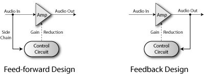
The principle of operation of the compressor
The signal falling into the compressor is divided into two copies. One copy is sent to the amplifier, in which the degree of amplification is controlled by an external signal, the second copy - forms this signal. It enters the device called side-chain, where the signal is measured, and the envelope is created based on this data describing the change in its volume.
So the most modern compressors are arranged, this is the so-called FEED-FORWARD type. In older devices (FEEDBACK type), the signal level is measured after the amplifier.
There are various analog control technologies (Variable-Gain Amplification), each with its advantages and disadvantages: lamps, optical using photoresistra and transistum. When working S. digital Sound (in the sound editor or DAW) their own mathematical algorithms can be used or the operation of analog technology can be emulated.
The main parameters of compressors
Threshold.
The compressor reduces the audio signal if its amplitude primaries a specific threshold value (THRESHOLD). It is usually indicated in decibels, with a lower threshold (for example, -60 DB) means that the sound will be processed than with a higher threshold (for example, -5 dB).
Ratio.
The degree of level decrease is determined by the Ratio parameter: Ratio 4: 1 means that if the input level is 4 dB exceeds the threshold, the output level will be higher than the threshold by 1 dB.
For example:
Threshold \u003d -10 db
Input signal \u003d -6 DB (on 4 dB above threshold)
Output signal \u003d -9 dB (on 1 dB above threshold)
It is important to keep in mind that suppressing the signal level continues and some time after it falls below the threshold level, and this time is determined by the parameter value release.
Compression with the maximum value of Ratio ∞: 1 is called Limiting. This means that any signal above the threshold level is suppressed before the threshold level (with the exception of a short period after a sharp increase in the input volume). For details, see below "Limiter".

Examples of various Ratio values
Attack and Release
The compressor provides certain control over how quickly it responds to changing the signal dynamics. The Attack parameter defines the time for which the compressor reduces the gain coefficient to the level, which is determined by the Ratio parameter. Release Defines the time for which the compressor, on the contrary, increases the gain coefficient, or returns to normal if the input signal level drops below the threshold value.

ATTACK and Release phases
These parameters indicate the time (usually in milliseconds), which will be required to change the strengthening to a certain amount of decibel, is usually 10 dB. For example, in this case, if ATTACK is set to 1 ms, to reduce the gain by 10 dB, 1 ms will be required, and 20 dB - 2 ms.
In many compressors, the Attack and Release parameters can be configured, but in some they are initially set and not regulated. Sometimes they are designated as "Automatic" or "Program dependent", i.e. vary depending on the input signal.
Knee.
Another compressor parameter: hard / Soft Knee. It determines whether the beginning of the application of compression is sharp (Hard) or gradual (Soft). Soft Knee reduces the slumbering of the transition from the raw signal to the signal subjected to compression, especially at high Ratio values \u200b\u200band sharp volume increases.

Hard Knee and Soft Knee Compression
PEAK and RMS.
The compressor can react to peak (short-term maximum) values \u200b\u200bor on the averaged input level. The use of peak values \u200b\u200bcan lead to sharp fluctuations in the degree of compression, and even to distortion. Therefore, compressors apply averaging function (usually this is RMS) input signal when comparing it with a threshold value. It gives a more comfortable compression, close to the human perception of the volume.
RMS is a parameter reflecting the average volume of the phonogram. From a mathematical point of view RMS (Root Mean Square) is the rms value of the amplitude of a certain number of samples:

Stereo Linking.
Compressor in Stereo Linking mode applies the same gain to both stereo channels. This avoids the displacement of the stereopanorama, which can be the result of the individual processing of the left and right channels. Such a displacement occurs if, for example, any loud element panted not in the center.
Makeup Gain.
Since the compressor reduces the overall signal level, the possibility of fixed gain at the output is usually added, which allows you to get the optimal level.
LOOK-AHEAD.
The Look-AHead function is designed to solve problems peculiar both too large and too small values \u200b\u200battack and release. Too much attacks do not allow you to effectively intercept transients, but too small may not be comfortable for the listener. When using the LOOK-AHEAD function, the main signal is delayed relative to the controller, it allows you to start compression in advance, even before the signal reaches the threshold value.
The only disadvantage of this method is the time delay of the signal, which in some cases undesirable.
Use of dynamic compression
Compression is used everywhere, not only in musical phonograms, but also everywhere, where you need to increase the overall volume, without increasing the peak levels where the inexpensive sound-reproducing equipment is used or a limited transmission channel (alert system, amateur radio, etc.) .
Compression is applied when playing background music (in stores, restaurants, etc.), where any noticeable volume changes are undesirable.
But the most important scope of applying dynamic compression is musical production and broadcasting. Compression is used to give the sound "density" and "Drive" for best combination tools with each other, and especially when processing vocals.
Vocal parties in rock and pop music are usually subjected to compression to highlight them on the background of the accompaniment and add clarity. A special type of compressor, configured only on certain frequencies - deesser, is used to suppress hissing background.
In the instrumental parties, the compression is also used for the effects that are not directly related to the volume, for example, the rapidly fading drum sounds can become more prolonged.
In electronic dance music (EDM), Side-chaning is often used (see below) - for example, the bass line can be controlled by a barrel or something similar to prevent the conflict of bass and drums and create a dynamic pulsation.
Compression is widely used in broadcast transmission (radio, television, Internet broadcasting) to increase the perceived volume while reducing the dynamic range of source audio (usually CD). Most countries have legal restrictions on the instant maximum volume, which can be broadcast. Typically, these limitations are implemented by constant hardware compressors in the ethereal chain. In addition, an increase in the perceived volume improves the "quality" of the sound from the point of view of most listeners.
see also Loudness War.

A consistent increase in the volume of the same song remandged for CD from 1983 to 2000.
Side-chaning
Another frequently found compressor switch is "Side Chain". In this mode, the compression of the audio does not occur depending on its own level, but depending on the signal level entering the connector, which is so usually called - Side Chain.

This can be found several applications. For example, vocalist Shepelvit and all the letters "C" stand out out of the overall picture. You skip his voice through the compressor, and the Side Chain connector serves the same sound, but missed through the equalizer. On the equalizer you remove all the frequencies, except for those used by vocalist when pronouncing the letter "C". Usually about 5 kHz, but can be from 3 kHz to 8 kHz. If then put a compressor into Side Chain mode, then the compression of the voice will occur in those moments when the letter "C" is pronounced. Thus, it turned out a device known as "Deesser" (DE-ESSER). This method of work is called "frequency dependent" (Frequency Dependent).
Another use of this feature is called "Ducker". For example, on a radio station, music goes through the compressor, and the words of DJ - through a side chain. When DJ starts chatting, the volume of music is automatically reduced. This effect can be successfully used in records, for example, reduce the volume of keyboard batches during singing.
Brick Wall Limiting
The compressor and the limiter are approximately the same, it can be said that the limiter is a high Ratio compressor (from 10: 1) and, usually, low attack time.
There is a BRICK WALL LIMITING concept - a very high ratio limiting (from 20: 1 and above) and a very fast attack. Ideally, it does not allow the signal to exceed the threshold level. The result will be unpleasant for rumor, but this will prevent damage to sound reproducing technology or excess bandwidth Channel. Many manufacturers integrate limiter devices for this purpose.

Clipper VS. Limiter, Soft and Hard Clipping

© 2014 Site
Or photographic latitude The photo material is the relationship between the maximum and minimum exposure values \u200b\u200bthat can be correctly captured in the picture. With reference to the digital photography, the dynamic range is actually equivalent to the ratio of the maximum and minimum possible values \u200b\u200bof the useful electrical signal generated by the photo seensor during the exposure.
The dynamic range is measured in the exposure steps (). Each step corresponds to doubling the amount of light. For example, if a certain camera has a dynamic range of 8 EV, this means that the maximum possible value of the useful signal of its matrix refers to the minimum as 2 8: 1, which means that the camera is capable of capturing within one frame objects differing in brightness No more than 256 times. More precisely, it can capture objects with any brightness, however, objects whose brightness will exceed the maximum allowable value will be released on a picture of dazzling white, and objects whose brightness will appear below the minimum value - coal black. Details and textures will be distinguishable only on those objects whose brightness is stacked in the dynamic range of the chamber.
To describe the relationship between the brightness of the brightest and most dark from the removable objects, not quite correct term "dynamic scene range" is often used. It will be more correct to talk about the brightness range or about the contrast level, since the dynamic range is usually the characteristic of the measuring device (in this case, the matrix of the digital camera).
Unfortunately, the brightness range of many beautiful scenes, with which we face in real life, can significantly exceed the dynamic range of digital cameras. In such cases, the photographer is forced to decide which objects should be worked out in all parts, and which one can be left outside the dynamic range without prejudice to creative design. In order to make the most effectively use the dynamic range of your camera, sometimes it may take not so much a thorough understanding of the principle of work of photosensor, how much developed artistic one.
Dynamic Range Factors
The lower boundary of the dynamic range is set by the level of its own noise of the photo seensor. Even the unlit matrix generates a background electrical signal, called dark noise. Also, interference occurs when the charge is transferred to an analog-to-digital converter, and the ADC itself introduces a certain error in the digitized signal - so-called. Noise sampling.
If you take a picture in a complete darkness or with a lid on the lens, then the camera will record only this meaningless noise. If you allow the minimum number of light to get to the sensor, photodiodes will begin to accumulate electric charge. The value of the charge, which means the intensity of the beneficial signal, will be proportional to the number of captured photons. In order for a snapshot, at least some meaningful details, it is necessary that the level of the useful signal exceeds the background noise level.
Thus, the lower boundary of the dynamic range or, in other words, the sensitivity threshold of the sensor formally can be defined as the output signal level at which the signal-to-noise ratio is greater than the unit.
The upper limit of the dynamic range is determined by the container of a separate photodiode. If, during the exposition, any photodiode will accumulate an electrical charge of limiting values \u200b\u200bfor itself, then the pixel of the image corresponding to the overloaded photodide is absolutely white, and further irradiation will not affect its brightness. This phenomenon is called clipping. The higher the frenetic ability of the photodiode, the greater the signal is capable of giveing \u200b\u200bat the output before the saturation reaches.
For greater clarity, we turn to the characteristic curve, which is a graph of the output signal dependency from the exposure. On the horizontal axis, the binary logarithm of irradiation obtained by the sensor is postponed, and on the vertical - binary logarithm of the magnitude of the electrical signal generated by the sensor in response to this irradiation. My drawing is largely conditional and pursues exceptionally illustrative purposes. The characteristic curve of the present photo seensor has a slightly more complex form, and noise level is rarely so high.

The graph is clearly visible two critical stiff points: in the first of these, the level of the useful signal crosses the noise threshold, and in the second - photodiodes reach saturation. Exposure values \u200b\u200blying between these two dots are dynamic range. In this abstract example, it is equal to how easy it is to notice, 5 EV, i.e. The camera is able to digest five doubling exposure, which is equivalent to 32x (2 5 \u003d 32) in brightness difference.
Exposure zones that make up the dynamic range are unequal. The upper zones are characterized by a higher signal-to-noise ratio, and therefore look clearer and more detailed than the lower. As a result, the upper limit of the dynamic range is very real and noticeable - clipping is wrapped lights at the slightest overexposition, while the lower boundary is increasingly sinking in the noise, and the transition to black color is far from so cut.
The linear dependence of the signal from the exposure, as well as a sharp yield to the plateau, are unique features of the digital photographic process. For comparison, take a look at the conditional characteristic curve of traditional photoplinka.

The shape of the curve and especially the angle of inclination greatly depend on the type of film and from the procedure of its manifestation, but the main thing that remains the difference between the film schedule from the digital - the nonlinear nature of the dependence of the optical density of the film from the exposure value remains unchanged.
The lower boundary of the photographic latitude of the negative film is determined by the density of the veil, and the upper one - the maximum achievable optical density of the photocloor; Rotate films - on the contrary. Both in the shadows and in the lights there are smooth bends of the characteristic curve, indicating the drop in contrast when approaching the boundaries of the dynamic range, because the angle of inclination of the curve is proportional to the contrast of the image. Thus, the exposure zones lying on the middle part of the schedule have a maximum contrast, while in the lights and shadows, the contrast is reduced. In practice, the difference between the film and the digital matrix is \u200b\u200bparticularly well noticeable in the lights: where in the digital image of the light is burned with clipping, the parts on the film are still distinguishable, although low-contrast, and the transition to a pure white color looks smooth and natural.
In sensitometry, even two independent terms are used: actually photographic latitudebounded by a relatively linear section of the characteristic curve, and useful photographic latitude, In addition to the linear section, also base and shoulder graphics.
It is noteworthy that when processing digital photos, it, as a rule, applies a more or less pronounced S-shaped curve, which increases the contrast in the halftone at the cost of its decrease in the shadows and lights, which gives a digital image a more natural and pleasant eye look.
Bigness
Unlike the matrix of the digital camera, human vision is peculiar, let's say, a logarithmic view of the world. Sequential doubling of the amount of light is perceived by us as equal changes in brightness. Light numbers can even be compared with musical octaves, because twofold changes of the sound frequency are perceived by rumor as a single musical interval. This principle employs other senses. The nonlinearity of perception is very expanding the human sensitivity range to the stimulus of various intensity.
When converting the RAW file (it does not matter, the camera tools or in the RAW converter) containing linear data, the so-called automatically applies to it. Gamma curve, which is designed to nonlinearly increase the brightness of the digital image, leading it in line with the peculiarities of human vision.

With linear conversion, the image is obtained too dark.

After gamma correction, the brightness comes to normal.
The gamma curve as it would stretch dark tones and squeezes light, making the distribution of gradations more uniform. As a result, the image acquires a natural look, but the noise and artifacts of sampling in the shadows inevitably become more noticeable, which is only exacerbated by a small number of brightness levels in the lower zones.
Linear distribution of brightness gradations.
Uniform distribution after applying a gamma curve.
ISO and dynamic range
Despite the fact that in the digital photography, the same concept of photosensitivity of the photographic material is used as in the photograph of the film, it should be understood that this is solely due to the tradition of tradition, since approaches to changing photosensitivity in digital and film photography differ in principle.
Improving ISO sensitivity in the traditional photography means replacing one film to another with a larger grain, i.e. There is an objective change in the properties of the photo material. In the digital camera, the sensitivity sensitivity of the sensor is toughly set it physical characteristics and cannot be changed literally. With an increase in ISO, the camera changes not real sensitivity of the sensor, but only enhances the electrical signal generated by the sensor in response to irradiation and correctly adjusts the digitization algorithm for this signal.
An important consequence of this is to reduce the effective dynamic range in proportion to an increase in ISO, because with a useful signal, noise is enhanced. If the ISO 100 digitizes the entire range of signal values \u200b\u200b- from zero to the saturation point, then with ISO 200, only half the capacity of photodiodes is accepted for maximum. With each doubling of the ISO sensitivity, the upper stage of the dynamic range is cut off, and the remaining steps are tightened to its place. That is why the use of ultra-high ISO values \u200b\u200bare deprived of practical meaning. With the same success, you can lighten the photo in the RAW converter and get a comparable level of noise. The difference between an increase in ISO and an artificial illumination of the picture is that with increasing ISO, the signal strengthening occurs before it is received in the ADC, and therefore the noise of quantization is not enhanced, unlike its own noise of the sensor, while in the RAW-converter, the amplification is subject to Including the mistakes of the ADC. In addition, a decrease in the digitization range means more accurate sampling of the remaining input values.
By the way, an ISO is available on some devices below the base value (for example, to ISO 50), it does not expand the dynamic range, and simply loosens the signal twice, which is equal to the snapshot in the RAW converter. This function can be even treated as harmful, since the use of submimic value of ISO, provokes a chamber to increase the exposure that, with the remaining unchanged threshold of the sensor, it increases the risk of getting clipping in lights.
True dynamic range
There are a number of programs like (DXO Analyzer, Imatest, Rawdigger, etc.) allow you to measure the dynamic range of a digital camera at home. In principle, this is not a great need, since the data for most cameras can be freely found on the Internet, for example, on the Dxomark.com website.
Should I believe the results of such tests? Quite. With the only reservation that all these tests are defined efficient or, if you can express it, the technical dynamic range, i.e. The relationship between the saturation level and the noise level of the matrix. For the photographer, the useful dynamic range is primarily important, i.e. The number of exposure zones that really allow you to capture some useful information.
As you remember, the threshold of the dynamic range is specified by the noise level of the photo seensor. The problem is that in practice the lower zones formally incoming in the dynamic range, contains everything too much noise so that they can be used to use. Here, much depends on individual squeezing - the acceptable level of noise each determines for itself.
My subjective opinion is that the details in the shadows begin to look more or less decent with the signal / noise ratio at least eight. On this basis, I determine for myself a useful dynamic range, as a technical dynamic range minus about three steps.
For example, if the mirror chamber according to the results of reliable tests has a dynamic range of 13 EV, which is very good for today's standards, then its useful dynamic range will be about 10 EV, which, in general, is also very thorough. Of course, we are talking about shooting in RAW, with minimal ISO and maximum bit. When shooting in JPEG, the dynamic range strongly depends on the contrast settings, but on average two or three steps should be discarded.
For comparison: color-traded photo shots have a useful photographic latitude of 5-6 steps; Black and white negative films give 9-10 steps when standard procedures manifestations and seals, and with certain manipulations - up to 16-18 steps.
Summarizing the above, let's try to formulate a few simple rulesCompliance with which will help you squeeze your camera from the sensor maximum performance:
- The dynamic range of the digital camera is fully accessible only when shooting in RAW.
- The dynamic range decreases with increasing light sensitivity, and therefore avoid high ISO values \u200b\u200bif there is no sharp necessity.
- Using higher bit for RAW files does not increase the true dynamic range, but improves the tonal separation in the shadows due to more brightness levels.
- Exposure to the right. Upper exposure zones always contain maximum useful information With a minimum of noise and should be used most effectively. At the same time, you should not forget about the danger of clipping - pixels that have reached saturation are absolutely useless.
And the main thing: it is not necessary to worry about the dynamic range of your camera. With a dynamic range, it is all right. Your ability to see light and competently manage exposure is much more important. A good photographer will not complain about the lack of photographic latitude, but will try to wait for more comfortable lighting, or will change the angle, or will use the flash, in a word, will act in accordance with the circumstances. I will tell you more: some scenes only won due to the fact that they do not fit into the dynamic range of the camera. Often an unnecessary abundance of parts is simply necessary to hide into a semi-grated black silhouette that makes a photo at the same time concisely and richer.

High contrast is not always bad - you only need to be able to work with it. Learn to exploit the disadvantages of equipment as well as its advantages, and you will be surprised how much your creative opportunities will expand.
Thanks for attention!
Vasily A.
POST Scriptum
If the article has been useful and informative for you, you can kindly support the project, making a contribution to its development. If you didn't like the article, but you have thoughts on how to make it better, your criticism will be accepted with no less gratitude.
Do not forget that this article is the object of copyright. Reprint and quoting is allowed if there is an existing reference to the original source, and the text used should not be selected or modified.