Arduino fingerprint sensor. Homemade anti-theft device on Arduino Uno and fingerprint sensors. Disconnection from COM port
To create a connection with the print sensor, an instruction from Josh Hew (direct loading instructions) was used.
To debug the work of the fingerprint scanner with the letterboard, it is necessary to synchronize.
The fingerprint sensor has its own memory for storing scanned pictures. So after the sensor starts to work, download this by adding it to the fingerprint database under the address 0. Open the control console on the computer and follow the pop-up prompts.
Codes - Blink Example:
/ * Library Example for Controlling The GT-51C3 Finger Print Scanner (FPS) * / #Include "FPS_GT511C3.H" #include "SoftWareSerial.h" // Hardware Setup - FPS Connected to: // Digital Pin 10 (Arduino RX, FPS TX) // Digital Pin 11 (Arduino TX - 560ohm Resistor FPS TX - 1000OHM Resistor - Ground) // This Brings The 5V TX Line Down to About 3.2V SO WE Dont FRY OUR FPS FPS_GT511C3 FPS (10, 11); void setup () (serial.begin (9600); fps.useserialdebug \u003d true; // So you can see the messages in the serial debug screen fps.open ();) void loop () (// FPS Blink LED Test FPS .Setled (true); // Turn on the LED Inside the FPS Delay (1000); FPS.Setled (False); // Turn Off The Led Inside The FPS Delay (1000);)
Codes - Enroll Example:
/ * Fps_enroll.ino - Library Example for Controlling The GT-511C3 Finger Print Scanner (FPS) * / #Include "FPS_GT511C3.H" #include "SoftWareSerial.h" // Hardware Setup - FPS Connected to: // Digital Pin 10 (Arduino RX, FPS TX) // Digital Pin 11 (Arduino TX - 560ohm Resistor FPS TX - 1000OHM Resistor - Ground) // This Brings The 5V TX Line Down to About 3.2V SO WE Dont Fry Our FPS FPS_GT511C3 FPS (10, eleven); void setup () (serial.begin (9600); delay (100); fps.open (); fps.setled (true); enroll ();) void enroll () (// Enroll Test // Find Open Enroll ID int english \u003d 0; fps.enrollstart (englid); // enroll serial.print ("Press Finger to Enroll #"); serial.println (enroll); while (fps.ispressfinger () \u003d\u003d false) Delay (100) ; bool bret \u003d fps.capturefinger (true); int iret \u003d 0; if (Bret! \u003d false) (serial.printLN ("Remove Finger"); fps.Enroll1 (); while (fps.ispressfinger () \u003d\u003d True ) Delay (100); serial.printLN ("Press Same Finger Again"); While (FPS.ispressFinger () \u003d\u003d False) Delay (100); Bret \u003d FPS.CaptureFinger (TRUE); if (Bret! \u003d FALSE) (Serial.printLN ("Remove Finger"); fps.Enroll2 (); While (fps.ispressfinger () \u003d\u003d true) Delay (100); serial.printLN ("Press Same Finger Yet Again"); while (FPS. Ispressfinger () \u003d\u003d false) delay (100); bret \u003d fps.capturefinger (true); if (Bret! \u003d False) (serial.printLN ("Remove Finger"); Iret \u003d fps.Enroll3 (); if (IRET \u003d\u003d 0) (serial.printLN ("Enrollin g successfull "); ) ELSE (Serial.print ("Enrolling Failed WITH Error Code:"); serial.printLN (IRET);)) Else Serial.printLN ("Failed to Capture Third Finger"); ) else serial.println ("Failed to Capture Second Finger"); ) else serial.println ("Failed to Capture First Finger"); ) void loop () (Delay (100000);)
Synchronization file:
Sketch registration file:
Stage 7: Programming the ATTINY85 processor
Attiny85 microchip is cheap, and fully compatible with Arduino pay, it is probably the best electric train from ever created!
The Arduino programmer is also needed to reflash the ATMEGA328 chip, which manages the work of the LCD display.
In the collected device, the ATTINY processor will perform very simple commands: check the presence of an ATMEGA signal and open the garage door when the signal is confirmed.
To program the work of the processor, it must be connected using macateboards To the programmer, together with the condenser 10 of the ICF, as shown in the picture below.
And then download final code and follow recommendations instructions from High-Low Tech.
After, output 13 on the Arduino board, connected to the LED, you need to translate to the HIGH state to track the light indication.
Final code for Attiny :
// FPSattiny by nodcah // Recieves a Brief Signal from the main module to close a relay void setup () (Pinmode (2, Output); // Indicator LED Through 10K Resistor Pinmode (4, Output); // Trasistor Pin That OpenS The Garage Pinmode (0, Input); // Input Delay (500); // Give Things Time to Start Up DigitalWrite (2, High); // Indicator LED) void loop () (if (DigitalLread (0)) (// Simple Pattern to Trigger The Transistor Delay (125); if (DigitalRead (0) \u003d\u003d FALSE) (Delay (55); // The Timings Are Off Because The Attiny "S Timer ISN" T Perfect If (DigitalLread ( 0)) (Delay (55); if (DigitalRead (0) \u003d\u003d False) (Delay (55); if (DigitalLread (0)) (Delay (55); if (DigitalRead (0) \u003d\u003d FALSE) (DigitalWrite (4, High); // transistor "Presses" The Button Delay (1000); DigitalWrite (4, Low); DigitalWrite (2, Low); Delay (1000); DigitalWrite (2, High);))))) ))
Biometric Castle - Final Code, Cutting Cover, Garage Preparation GPS clock on Arduino Biometric Castle - Scheme and Assembly LCD Display
To create such a project, the author had to modify the launch system of its vehicle. The main connection is the IG conductor from the ignition lock, through which the supply voltage is given to the voltage controller, after which the Arduino itself is already on the Arduino itself to turn it on, as well as turning on the finger scanning sensor. If the finger scanning is successfully the system activates the relay block, and it controls the starter relay. Now you can start the car. The sensor operates 10 seconds, and it can be repeated repeatedly repeating the ignition start cycle. If for the allotted time the sensor did not find a fingerprint or it does not match the specified, then the start-up system will be disabled, and the engine start does not occur.
Since each car has its own launch configuration system, then you must look at electrical circuit Before modifying the engine start system.
This article describes the connection of the anti-theft device on the 2-door coupe Mitsubishi Lancer 2000.
Materials:
- Arduino Uno.
- Fingerprint sensor.
- Power supply.
- relay block.
- NPN transistor BC547B
- resistor 1 com


Connection diagram:
The scheme is slightly modified in accordance with the components used. It should be remembered that it is valid only for this car model.

Step 1 Preparation of software components:
In the Arduino IDE development environment, the library is downloaded and added.
A file from the Blank.ino library in Arduino, which will serve as an interface between the sensor and the microcontroller.
A program is installed, and the sensor connects to Arduino as shown in the diagram. After that, the fingerprint is loaded through the installed program.

Now the sensor was connected as shown in the following scheme. After that, the author proceeds to download the main program. The LED with the resistor is connected to the output 12.
The program will work mainly by educational material ADAFRUTI FINGERPRINT. The program code added except the sensor shut-off timer in 10 seconds. Download Code can be under the article.

Step 3 Assembly:
Part 1:
For starters, screws are twisted under dashboard. The bottom of the panel is removed, and the sensor will be placed in the free space.


Part 2:
In the selected location for the sensor, the zone is cut for its reliable installation.


part 3:
Arduino board is installed behind the fingerprint sensor. The place for installing Arduino was a little accumulative that the board could take the correct position.


part 4:
The adjustable power source is installed behind the dashboard on the driver side.

part 5:
The remaining components of the equipment are connected according to the scheme at the beginning of the article.


Step 4 Installation:
The required wires are connected, and the device is installed under the dashboard. The author is convinced that there is no short circuit.
If you use a relatively old device, you should not be upset ahead of time. Instead of exchanging old laptop On a more modern, with an already built-in biometric sensor, you can connect to it USB.
PQI Mini USB Fingerprint Reader is an excellent choice for those who want to give old equipment to the second life. The scanner was created specifically to work with new feature Hello available on devices with Windows 10. However, the device supports both operating versions. windows systems 7 and 8.
One of the main advantages of the sensor is that it has the ability to 360-degree scanning. Therefore, you do not have to worry about how best to connect the device to the PC. Use the nearest USB port And start working. When a scanner needs a fingerprint, it will automatically turn where it is necessary and compares the data obtained with a saved copy.
PQI Mini USB FingerPrint Reader can store up to 10 different profiles in memory. Therefore, the device is great for sharing or those cases when you need to scan an additional finger (if the "main" is contaminated or injured).
PQI Mini USB Fingerprint Reader is available at a very democratic price, which makes it an excellent choice for those who are looking for a start model. In addition, the scanner is portable enough to carry it with them without any problems.
Verifi P2000 Fingerprint Reader

If you use a stationary computer on which it is not so easy to get to USB ports, then pay attention to the Verifi P2000 Fingerprint Reader. It is easily connected to the PC, and the main thing can be placed close to the computer, for more comfortable use.
The scanner is made of impact resistant metal and will serve not one year. Despite the solid design, it has a good fingerprint recognition coefficient. Therefore, you do not have to constantly change the position of the finger only to achieve a complete coincidence. In most cases, it will be enough to spend on the sensor only.
When creating a P2000 model, Verifit planned to make a solid and durable device so that it does not affect the scanning process and the accuracy of recognition of results. Verifi P2000 Fingerprint Reader is enough portable devicewhich can be easily wearing with you. In addition, it is compatible with much more computers than other similar models.
KENSINGTON VERIMARK.

For an incredibly small fingerprint scanner, Kensington Verimark has almost everything you need for comfortable work. The model boasts support for 360-degree scans and a small size. But most importantly, what does Kensington Verimark make such valuable, additional functionality.
All received data is stored in encrypted form. When the sensor scans the fingerprint, he immediately encrypts it. Interrupt this process It is impossible, so hack software or hardware and extract biometric data will not work.
In addition, the device uses a special template to decrypt the scans, which is only from the manufacturer. This makes it more protected from hacker attacks and other attempts to obtain unauthorized access.
The scanner supports working with relatively old ports regardless of the release version. If you use the model C, then with uSB-C adapter to USB-A device You can connect to a relatively old laptop or computer without supporting more modern USB ports.
BENSS FINGERPRINT READER ANALYZER
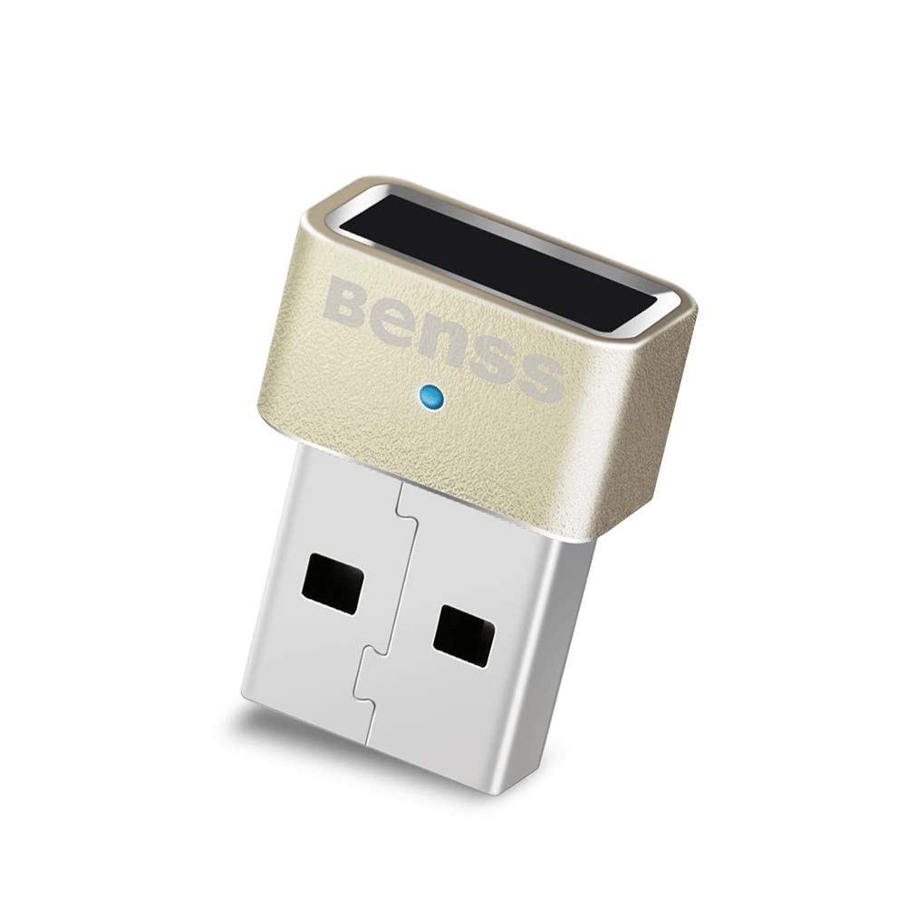
BENSS FINGERPRINT READER ANALYZER is another scanner who is able to facilitate your life and get rid of the heap of problems. As a rule, simple models first make one checkout, after which they compare all subsequent prints with the initial result. This means that if with the original picture (with which all other scans are compared) something will happen, the probability of the coincidence of the final results will greatly fall.
BENSS FingerPrint Reader Analyzer works through a self-learning algorithm that automatically creates and updates your profile with each touch. The longer you use the device, the more accurate the results will be. Thanks to this, the scanner is harder to deceive with the help of fake fingerprints. Since the sensor constantly scans your finger and updates the database, it immediately detects attempts to obtain unauthorized access.
This is one of the most effective devices for confronting hacker attacks. His factor of false pass (False Acceptance Rate) is less than 0.002%, which means that it will really try to hack the device. At the same time, it does not greatly complicate the work, its FRR coefficient (False Rejection Rate - a refusal to access a person registered in the system) is only 3%.
IDEM BIOSCAN Compact.

If you are looking for a scanner with caustomization capabilities, I will like the Idem BioScan Compact. To expand its basic features and get additional functionality, it is enough to download special software from the manufacturer's official website.
After that you can encrypt on the computer separate files and folders and also keep in special Program Login and password data to access websites. So you can log in to any Internet portals using the usual touch of the finger to the sensor.
Even if you do not take additional functionality into account, the BioScan Compact is considered a worthy model. The device can store up to 10 different fingerprints, boasts in small dimensions, as well as built-in protection for recognizing fake biometric data.
Blucoil Secugen Hamster Pro 20

Blucoil Secugen Hamster Pro 20 is the perfect fingerprint scanner for professional needs. Due to the fact that the model offers improved security settings, its cost is almost twice as high as other devices from our list.
In addition, it is one of the few scanners with official Linux support. Therefore, no matter what exactly operating system You use the sensor is suitable for performing any tasks.
SECUGEN HAMSTER PRO 20 is a shock-resistant device with scratch protection, ingestion of water and dust. The scanner is able to track the traces remaining after the previous checks and reject fuzzy results.
In addition, Blucoil Secugen Hamster Pro 20 is an energy-saving device, so it turns off automatically if no one uses them for a long time.
Additional safety
In recent years, a huge amount of mobile and desktop devices with built-in fingerprint scanners have been released and their number is only grown every year. If your computer has no built-in sensor to recognize biometric data, then you should not be upset. There is a huge variety of USB scanners for PCs and laptops that are compatible with almost all popular models.
Since I do not have a car, I don't need to carry the keys everywhere. Because of this, it turned out that I turned out to be without keys out several times and I had to wait until someone from relatives would return home and let me let me, and at some point I decided that I needed something to do something and Designed a homemade garage castle.

In this project, I will tell you how to make a castle with a fingerprint to the front door.
Step 1: Materials


Here is a list of essential materials and tools.
Electronics:
- Fingerprint Scanner (and JST Connector)
- LCD set (C ATMEGA328)
- Attiny85.
- NPN transistor
- SPECIAL SPECIAL
- Wire for speaker
- Case (in step 9 there will be files for 3D printing)
- Copper Flee
- Voltage regulator 5V.
- Battery 9V.
- 9V battery connector
- SPDT switch
For convenience, I will apply a ready Wishlist on the sparkfun website.
Tool:
- Soldering iron and solder
- Insulating tape
- Wires and jumpers
- Plippers / Stripper
- Prototyping board
- Different resistors
- Screws
- Drill
- Multiple LEDs for Testing
- FTDI 5V fee
- Gun with hot glue
- Access to the 3D printer
- Optional: socket for integrated circuits (8-pin for Attiny and 28-pin for ATMEGA)
- Optional: Another Arduino board / 10UF capacitor (details in step 5)
Step 2: Device Scheme


Acquired in SPARKFUN LCD-set walked with ATMEGA328, controlling display. ATMEGA328 is quite powerful and can be used not only to control the display, but also for other tasks. In view of this, we can use it instead of Arduino for communication with the fingerprint scanner and send commands to attiny85, control the display and the sake.
So that the biometric door lock does not work all the time, I embed a switch in it, triggered at the moment when the case closes. If the case is closed - food on the device is not served, and we save battery resources.
Important note: Fingerprint scanner works at a voltage of 3.3V, so I recommend using a voltage separator that will convert signals from ATMEGA to 3.2V. The voltage separator consists of a 560 ohm resistor between the D10 / second nipper pin and a resistor by 1 kΩ between the GND / second nickname pin.
LCD pinout:
- D10 - PIN 1 scanner (black wire)
- D11 - PIN 2 scanner (through voltage separator)
- D12 - attiny85.
- D13 - Film
Attiny85 pinout:
- PIN 5 (0 in program code) - Login with ATMEGA
- PIN 3 (4 in Program code) - Transistor / Yellow LED
- PIN 7 (2 in the program code) - LED indication
Step 3: Collect Components from LCD Dial

Step name says itself: Handy-Dandy Quick Start / Assembly Guide
Step 4: Collect the scheme on the prototyping board


Placement of components on the board remains yours, just try to solder the wires so that they look in one direction and not climbed.
After the assembly, I covered the top and bottom of the board with hot glue - it fastened and isolated the elements of the circuit. Hot glue will not hurt a chip.
As with the main board, solder all to the Attiny board and apply hot glue to fix and isolation of components. The voltage regulator can be very hot, so it will be a good idea not to apply hot glue on it and the surfaces located next to it. It is also better not to cover hot glue attiny card, because you may want to remove and reprogram it.
Step 5: Programming ATMEGA328

As already mentioned in step 2, the ATMEGA328 has a sufficiently strong processor and enough Pins to control the LCD, while it controls other additional components. To achieve this, you need to program the chip.
If you have Arduino Uno or Duemilanove, you can simply remove the chip from them and replace it with the one in the set. Or you can find FTDI Basic Breakout fee (5V) and soldering nozzles to her side (see pictures in step 3)
You will also need to pour code in Duemilanove W / ATMEGA328 mode.
Code below - working programm To verify the device's performance.
#Include "LiquidCrystal.h" LiquidCrystal LCD (2,3,4,5,6,7,8); void setup () (Pinmode (9, Output); // Backlight Pinmode (13, Output); // Cook LCD.Begin (16, 2); // 16 Signs in width, 2 in the height of DigitalWrite (9, HIGH) ; // Turn on the LCD.Print ("Hello World!"); ); LCD.Print ("buzzer is on"); Tone (13, 262, 1000); Delay (1000); lcd.clear (); lcd.print ("buzzer is off"); delay (1000);) Files
Step 6: Configure Fingerprint Scanner

For communication with the scanner, I used this library. Direct download link.
To check the performance of the code, download this test program "blinking".
The print scanner has its own built-in memory for data storage. So after you make sure the scanner works, download this program to add your imprint to the database for ID # 0. Open the serial console and simply follow the instructions.
LED flashing program for scanner check
/ * This simple code will turn on and turn off the LED. It is used to understand whether communication works. * / #Include "FPS_GT511C3.H" #include "SoftWareSerial.h" // Iron Setting - Finger Scanner Connected from: // Digital Pin 10 (Arduino RX, FPS TX) // Digitize Pin 11 (Arduino TX - Resistor 560ohm FPS TX - resistor 1000OHM - GND) // It lowers 5V TX to about 3.2V and we will burn our FPS_GT511C3 FPS scanner (10, 11); void setup () (serial.begin (9600); FPS.useRialDebug \u003d True; // You can see messages on the FPS.open sequential debug screen ();) void loop () (// Test flashing LEDs for FPS scanner. SETLED (TRUE); // Includes LED inside the Delay scanner (1000); fps.setled (false); // Turns off LED inside the Delay scanner (1000);)Data registration program in the scanner
#include "FPS_GT511C3.H" #include "SoftWareSerial.h" // Iron Setup - Finger Scanner Connected from: // Digital Pin 10 (Arduino RX, FPS TX) // Digitize Pin 11 (Arduino TX - Resistor 560OHM FPS TX - Resistor 1000OHM - GND) // This lowers 5V TX to about 3.2V and we will burn our FPS_GT511C3 FPS scanner (10, 11); void setup () (serial.begin (9600); delay (100); fps.open (); fps.setled (true); enroll ();) void enroll () (// Test registration // Search for open ID Int enrollid \u003d 0; fps.enrollstart (englid); // Register serial.print ("Press finger to engl #"); serial.printLN (Enrolid); while (fps.ispressfinger () \u003d\u003d false) Delay (100); BOOL BRET \u003d FPS.CAPTUREFINGER (TRUE); int iret \u003d 0; if (Bret! \u003d false) (serial.printLN ("Remove Finger"); fps.Enroll1 (); while (fps.ispressfinger () \u003d\u003d true) Delay (100); serial.printLN ("Press Same Finger Again"); while (fps.ispressfinger () \u003d\u003d false) Delay (100); Bret \u003d FPS.CaptureFinger (True); if (Bret! \u003d FALSE) ( Serial.PrintLN ("Remove Finger"); fps.Enroll2 (); while (fps.ispressfinger () \u003d\u003d true) delay (100); serial.printLN ("Press Same Finger Yet Again"); while (fps.ispressfinger () \u003d\u003d false) Delay (100); Bret \u003d FPS.CaptureFinger (TRUE); if (Bret! \u003d false) (serial.println ("Remove Finger"); iret \u003d fps.Enroll3 (); if (IRET \u003d \u003d 0) (serial.printLN ( "Enrolling Successfull"); ) ELSE (Serial.print ("Enrolling Failed WITH Error Code:"); serial.printLN (IRET);)) Else Serial.printLN ("Failed to Capture Third Finger"); ) else serial.println ("Failed to Capture Second Finger"); ) else serial.println ("Failed to Capture First Finger"); ) void loop () (Delay (100000);) filesStep 7: Programming Attiny85


Attiny85 is something like a cheap Arduino, assembled in one chip. Attiny85 can be programmed by another Arduino, including ATMEGA328, which is in our LCD set. In the project, it is used to start very simple commands: check the signal from ATMEGA and open the gate if the signal is correct.
To program it, connect everything according to the attached photos. Then download required files And follow this instruction.
After loading the code, PIN 13 on Arduino (built-in LED) should turn around, notifying that the code is loaded.
Final code:
// Gets a brief signal from the main module to close the Void Setup () relay (Pinmode (2, Output); // LED display via a 10K Pinmode resistor (4, Output); // PIN of the steakistor, opening the Pinmode garage (0, Input ); // Enter Delay (500); // Giving a device Time for starting DigitalWrite (2, High); // LED display) void loop () (if (DigitalRead (0)) (// Simple Pattern for Switching Transistor Delay (125); if (DigitalRead (0) \u003d\u003d FALSE) (Delay (55); // Waiting, since the Attiny timer is not ideal (Digitalread (0)) (Delay (55); if (DigitalRead (0) \u003d \u003d false) (Delay (55); if (DigitalRead (0)) (Delay (55); if (digitalread (0) \u003d\u003d FALSE) (DigitalWrite (4, High); // Transistor "Pries" the Delay button (1000 ); DigitalWrite (4, Low); DigitalWrite (2, Low); Delay (1000); DigitalWrite (2, High);))))))) Files
Step 8: Final code
The following is attached program for Arduino, which I wrote using the scanner and display libraries. So that it was clear what happens in every part of the program, I tried to comment out in the best possible way. After loading this code, everything should earn and everything will be done - integrate the system at the door.
Warning: If the scanner library does not work, then try using old version IDE Arduino.
Code for ATMEGA238:
#include "LiquidCrystal.h" // #include display library "fps_gt511c3.h" // FPS library (print scanner) #include "SoftWareSerial.h" // Used by the library of the scanner // Configure Pins Display and LiquidCrystal LCD Scanner (2, 3, 4, 5, 6, 7, 8); // Pickup Display FPS_GT511C3 FPS (10, 11); // RX, TX Boolean isfinger \u003d false; // TRUE If the FPS library will delay the finger on the scanner // Pins Const int buzzerpin \u003d 13; Const int backlightpin \u003d 9; Const int attinypin \u003d 12; Const String iDNames \u003d ("Self", "Bro", "Ryan", "Mom", "Dad", "Auntie", "Grandma", "Zeide", "Person", "Person", "thumb"); Void setup () (// Configure Pinmode Outputs (Buzzerpin, Output); Pinmode (BacklightPin, Output); Pinmode (attinypin, output); // for debugging //serial.begin(9600); fps.useserdebug \u003d false; / / becomes True for debugging FPS via serial port // Initialization of LCD.Begin libraries (16,2); DigitalWrite (Backlightpin, High); // LCD FPS.open () highlighting; FPS.Setled (TRUE); // LED on FPS // Download sound for (int i \u003d 0; I<30; i++){ tone(buzzerPin, 50+10*i, 30); delay(30); } tone(buzzerPin, 350); //вывод стартового сообщения lcd.print("Put your finger "); //команда вывода на экран lcd.setCursor(0, 1); //устанавливаем курсор на нулевую колонку первой строки lcd.print(" on the scanner "); delay(150); noTone(buzzerPin); //останавливаем стартовый звук } void loop(){ //сканируем и распознаём отпечаток, когда приложен палец waitForFinger(); lcd.clear(); //очищаем экран и устанавливаем курсов в положение 0,0 fps.CaptureFinger(false); //захватываем отпечаток для идентификации int id = fps.Identify1_N(); //идентифицируем отпечаток и сохраняем id if(id <= 10){ lcd.print(" Access granted "); //сообщение об успехе lcd.setCursor(0,1); //выводим на экран имя когда дверь открывается String message = " Hey " + idNames + "!"; lcd.print(message); tone(buzzerPin, 262, 1000); delay(1500); //отправляем сигнал для открытия двери digitalWrite(attinyPin, HIGH); //первый импульс синхронизирует задержку (10ms) delay(5); digitalWrite(attinyPin, LOW); delay(3); digitalWrite(attinyPin, HIGH); //следующие два - открывают дверь delay(15); digitalWrite(attinyPin, LOW); delay(5); digitalWrite(attinyPin, HIGH); delay(10); digitalWrite(attinyPin, LOW); delay(1000); lcd.clear(); lcd.print("Don"t forget to "); lcd.setCursor(0,1); lcd.print(" shut me off! "); delay(2000); waitForFinger(); //нажмите чтобы продолжить запись while(true){ //сохраняет новый отпечаток //выводит сообщение на экран lcd.clear(); lcd.print(centerText("So you want to")); lcd.setCursor(0,1); lcd.print(centerText("scan a new one?")); delay(2000); //Скопировано и слегка модифицировано из примера регистрации данных: int enrollid = 11; //выбираете какой id переписать\создать //отпустите палец, когда хотите записать id/имя, напечатанное на экране waitForFinger(); //ждёт, когда будет нажат fps while(enrollid==11){ for (int i = 1; i1){ lcd.print(i); enrollid = i-1; break; } } } //предупреждение, если в данном слоте уже есть данные if(fps.CheckEnrolled(enrollid)){ lcd.clear(); lcd.print(" Warning! ID #"); lcd.print(enrollid); lcd.setCursor(0,1); lcd.print(" has data. OK? "); delay(2500); waitForFinger(); //ждёт, когда будет нажат fps fps.DeleteID(enrollid); //удаляет данные delay(100); } //Enroll fps.EnrollStart(enrollid); lcd.clear(); lcd.print("Place finger to "); lcd.setCursor(0,1); lcd.print("enroll #"); lcd.print(enrollid); //выводит id, который был добавлен waitForFinger(); //ждёт, когда будет нажат fps //захватывает отпечаток и сохраняет его в память трижды для точности данных bool bret = fps.CaptureFinger(true); //картинка высокого качества для записи int iret = 0; //в случае ошибки if (bret != false){ //первая регистрация lcd.clear(); lcd.print(" Remove finger "); fps.Enroll1(); while(fps.IsPressFinger() == true) delay(100); //ждёт пока уберут палец lcd.clear(); lcd.print(" Press again "); waitForFinger(); //ждёт, когда будет нажат fps bret = fps.CaptureFinger(true); if (bret != false){ //вторая регистрация lcd.clear(); lcd.print(" Remove finger "); fps.Enroll2(); while(fps.IsPressFinger() == true) delay(100); lcd.clear(); lcd.print("Press yet again "); waitForFinger(); bret = fps.CaptureFinger(true); if (bret != false){ //третья регистрация iret = fps.Enroll3(); if (iret == 0){ //проверяет, были ли какие-нибудь ошибки lcd.clear(); lcd.print(" Success! "); delay(2000); beep(); //выключает Ардуино } else{ //запускает этот код в случае любой ошибки lcd.clear(); lcd.print("Fail. Try again "); delay(1000); } } lcd.clear(); lcd.print(" Failed 3rd "); //ошибка на третьей записи delay(1000); } lcd.clear(); lcd.print(" Failed 2nd "); //ошибка на второй записи delay(1000); } lcd.clear(); lcd.print(" Failed 1st "); //ошибка на первой записи delay(1000); } } else{ lcd.print("Fingerprint is"); //если отпечаток не распознан lcd.setCursor(0,1); lcd.print(" unverified "); delay(2000); lcd.clear(); lcd.print("Please try again"); lcd.setCursor(0,1); lcd.print("Use your pointer"); //pointer - указательный палец (можете использовать любой и заменить это слово) delay(500); } delay(250); } void beep(){ //издаёт звуки, чтобы кто-нибудь закрыл кейс lcd.clear(); lcd.print("Please close the"); lcd.setCursor(0,1); lcd.print(" case! "); for(int i=0;i=80 && !fps.IsPressFinger()){ beep(); } } timer = 0; //обнуляет таймер как только функция завершится } String centerText(String s) { //центрует текст на дисплее, чтобы он лучше смотрелся while(16-s.length()>1) (// If the text needs the center S \u003d "" + s + ""; // evenly adds spaces on both sides) Return S; ) Files