Doorbell from mobile phone. Doorbell from the old phone. We make a wireless doorbell do it yourself
Electronic telephones fail for different reasons. And it is no longer able to repair the phone, or it just has a different one, more perfect will work for a long time. But if the old device is not yet thrown, then it can be used. As a rule, the electronic telephone consists of a diagram of a dialer and keys, as well as a conversational scheme. When the signal arrives from the telephone station, the call device is triggered, in other words, an electronic call. This part of the apparatus will come in handy. The calling device of the phone is often built on a specialized integrated circuit (IP) of the type KR1436AP1.
The meal of the microcircuit enters a special power knot with hysteresis. It provides the power of the rest of the nodes: LC generator, RF generator and output amplifier. The occurrence of sound oscillations is provided with two RCs. HF generator with its RC chain, which connects to the terminals 3 and 4, generates pulses with a frequency of about 10 Hz. They control the operation of the RF generator with the main frequency (F1) defined by the RC chain connected to the outputs 6 and 7. Thus, at the output of the second generator, pulses with alternating frequencies F1 and F2 are produced. F2 / F1 \u003d 1.25 frequency ratio. As a result, at the output of the microcircuit, the characteristic sound of trill is obtained. The CR1436Ap1 microcircuit is made in a miniature DIP-8 case. The main electrical parameters are shown in Table 1. Briefly consider the processes in the call diagram shown in Fig. 2. The voltage of the AC 220 V, 50 Hz arrives through the call button and the harvesting chain of the Condrumators C1 and C2 and resistors R1 and R2. Next, the variable voltage is straightened by the bridge rectifier on VD1-VD4 diodes, the limit of the VD5 stabitron, and a constant supply voltage of the chip is formed on a smoothing capacitor C3. Upon admission to the supply voltage of the appropriate value, it produces pulses sound Frequencywhich from exit 8 through the separation capacitor C6 goes to the transformer T. It is designed to match the high-alone IP output with a dynamic head of the resistance of 8 ohms. The transformation coefficient of the matching transformer at the maximum feed voltage should be about 150 (1300: 8). However, a sufficiently high load capacity of the IC type KR1436Ap1 (as well as its analogues) allows the transformer from the telephone with a coefficient of transformation volume 220: 29 (especially with reduced supply voltage ~ 15 V). Electrical parameters The electronic call schemes are shown in Table 2. If you wish, you can change the sound of trill with the help of RC chains. The low-frequency generator frequency is calculated by the formula FC \u003d 1 / (1.23R4C4), and the frequency of the high-frequency is formula F1 \u003d 1 / (1.51R5C5). Feature of the considered electronic call scheme on the formator chip call signal Phone type kr1436aap1 is increased electrical safety. In traditional electric door calls, the button is turned on into the rupture of the ring chain, and there is a network potential on it. Therefore, when damaged the button of the button (and this is very real in our time), electric shock is possible through the low-level parts of the call scheme. In the electronic call diagram, the button is also included in the chain rupture, however, in case of damage to the button of the button and random touch to the current parts, electricity It will pass through the R1 resistor and C1 (or C2 and R2) condenser). When capacity 0.47 μF, the resistance of the capacitor is about 6.7 com. Thus, the current flowing in the circuit will be significantly less. And in conclusion, a few words about the manufacture of calls and analogues of the elements used. In some phones, the circuit of the call signal is located on the shared board of the device compactly, and it can be cut and placed in the call case. In the case of making a call, it should be borne from the new parts that the list of elements, analogs and permissible replacements is shown in Table 3. The call is properly collected from the suitable parts immediately starts working. Otherwise, it is necessary to file from the power supply voltage about 15 V and look for a fault.
Igor Koltsov
This e-mail address is protected from spambots, you need JavaScript @ Net.ru to view it.
We make a wireless doorbell do it yourself
The author of the decision shares the experience of making the Wireless Turning on the doorbell with your own hands using the whale master modules. After moving B. new apartmentThe first thing I decided to set the call. But this task was not easy. The fact is that the developer has installed a call button only at the entrance door, and there was no buttons from the input door tambour. Since the old call was electromechanical and turned on by a diagram through the button, it was required to lay an additional wire. But an attempt to lay in Tambouri Wire was crowned with failure. The walls of the tambura were made of durable concrete, and the ordinary drill with the function of the perforator simply bounced from the wall. In order not to spend money on acquiring an expensive professional tool, it was decided to buy a simple Chinese wireless call. Plus the absence of extra wires in sight. But it also turned out to be not easy. Cheap calls had poor sound quality and a banal set of melodies that get tired after the first month of operation. In the end, they decided to temporarily leave their old good electromechanical bell. It would be all over this, but the lack of an external button at the Tambour door periodically made himself felt. It was decided to make the wireless turning on the call.
https: // Website / Blog / Articles / Staryj-Drug Luchshe-Novykh-Dvukh
Articles
We make a wireless doorbell do it yourself
After moving to a new apartment, the first thing I decided to set the call. But this task was not easy. The fact is that the developer has installed a call button only at the entrance door, and there was no buttons from the input door tambour. Since the old call was electromechanical and turned on by a diagram through the button, it was required to lay an additional wire. But an attempt to lay in Tambouri Wire was crowned with failure. The walls of the tambura were made of durable concrete, and the ordinary drill with the function of the perforator simply bounced from the wall. In order not to spend money on acquiring an expensive professional tool, it was decided to buy a simple Chinese wireless call. Plus the absence of extra wires in sight. But it also turned out to be not easy. Inexpensive calls had poor sound quality and a banal set of melodies that get tired after the first month of operation. In the end, it was possible to find a suitable call with more nice sound. Oddly enough, it was electromechanical, only with a built-in wireless module. Everything is wonderful, but disappointed the price of this call, he cost 9000 rubles.
As a result, we decided to temporarily leave your old good electromechanical bell. It would be all over this, but the lack of an external button at the Tambour door periodically made himself felt. It was decided to make the wireless turning on the call.
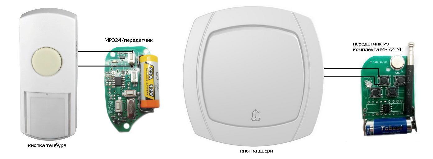
To implement a project from the range wireless modules The whale whale was selected several devices operating in the range of 433 MHz: and.

I think it will immediately arise the question for which the MP220V sensor needs. Actually everything is simple, the developer of this sensor laid into it additional opportunityNamely: With a simple soldering iron manipulation, the sensor turns into a compact built-in power supply with a current to 80 mA and a voltage of 5V or 12V to choose from. By default, the module is configured to voltage 5V. Since there are few places in the call case, it was selected to power the MP324M receiver.
But each good thing has its drawback, in this case it is the absence of galvanic junction from the network. Therefore, when setting up, you must follow the rules of electrical safety. And the installation of the scheme is made only in a de-energized state. To translate this module into the power source mode, it is necessary to cross the jumpers -v, RL and + V, RL to position 1-2. In principle, nothing prevents the use of a fee from 5V cell phone adapter, if the place allows.
For compactness, the variable resistor of the MP246 power module can be dismantled. Having installed a jumper from an ordinary mounting wire instead or from the output of a DIP resistor, which actually was done.
To build a circuit, you will need one DIP resistor with a par value of 10-15 kΩ and an electrolytic capacitor with a rating of 47 μF voltage not lower than 6V. In principle, the capacitor can be excluded from the scheme. But the pulse duration, at the MP324M receiver output, it seemed large to me, therefore this chain was installed. Reducing and increasing the capacitance of the capacitor can be adjusted pulse duration. Since different calls have a different design, it may be needed when setting up the sound. The resistor installed parallel to the chain, performs the discharge of the electrolytic capacitor, for the possibility of repeated call response.
Connection diagram:

After assembling the call control circuit, connect the design to the network and register the receiver. To register, press the button briefly on the receiver, then press the buttons on the transmitter, after a few seconds there will be a pairing. Now, when you press the first button on the transmitter, the call must work. Thus, add and check the second remote.
Photo layout modules in a call:

After checking, the call case closes and is installed in place:

You ask how we can feed the collected device. After all, the voltage appears on the call connection line only when the button is pressed when the call is pressed. In fact, everything is simple, the power of the call we will provide when modifying the button.
To begin with, it is advisable to de-energize the area of \u200b\u200bthe chain, where we will produce a modification. We remove the button out of the box and the two standard wires with each other are insulating them with a tape. Such a connection will give us constant nutrition 220V. Consumption current, in standby mode, makes tens of microampers. Therefore, constant inclusion will not affect the payment of electricity.

Now you disassemble the transmitters and sweep the two wires parallel to the first buttons. The resulting conclusions we clean and connect to contacts shot buttons. For greater reliability, the transmitters can be wrapped with one layer of tape.
Transmitter diagram to call buttons:
Now install the button in place and check the work of the call.
In the same way, we collect the second button and fix its body to a tambour door, for example, for two-way tape. Although I still managed to drill the wall on a small depth and fix on two small screws.

Well, that's all, you can use.
If after a couple of years it will stop working one of the buttons, do not panic, just the time to replace the batteries. Transmitters are powered by a voltage of 12V from the element 27a, which can be freely purchased in any supermarket. I think there will be no problem with this. In this scheme, elements work for a year. And since I don't use the call, I think that in such a mode will work at least a couple of years.
The device can be viewed on the video.
The site is in test mode. We apologize for failures and inaccuracies.
We ask you to write to us about inaccuracies and problems through the feedback form.
Polyphonic apartment call from cell phone.
Cell phones with a faulty high-frequency part, with a broken display and other damage or factory marriage, not allowing them to be directly intended, often simply emit or disassembled on parts, since the cost of repair is comparable to the price of the new apparatus. The author of the article extended the life of such a phone, turning it into a polyphonic apartment call. In the same way, you can use partially defective cellular telephone Any type, if it has the ability to play the melody stored in the memory, choosing them by pressing the buttons. When you click on the Cancel button, the cell phone (the author used the Samsung SGN-X100) reproduces the melody selected randomly of several dozen stored in memory. With the opening of the door, the melody breaks down. If you press the button in a special way, the call identifies the coming and will lose the melody assigned to it. In addition to the phone, the device is installed in the device, the microcontroller, umzch and chargerpowered amplifier and periodically rechargeable phone battery. Element base: PIC16F84 chips, KA2209, CT973A transistors (2 pcs.) KP501A (2 pcs.), Optocoule AOT1BS (2 pcs.) And aou160a. Dana drawing pCB, the photo of the phone board, explaining the connector connection to it to connect to other parts of the device, and the microcontroller's hex file. The source text and program codes will be posted on the FTP server editorial
Electronic telephones fail for different reasons. And it is no longer able to repair the phone, or it just has a different one, more perfect will work for a long time. But if the old device is not yet thrown, it can be used ... as a door electronic call!
The meal of the microcircuit enters a special power knot with hysteresis. It provides the power of the rest of the nodes: LC generator, RF generator and output amplifier. The occurrence of sound oscillations is provided with two RCs. HF generator with its RC chain, which connects to the terminals 3 and 4, generates pulses with a frequency of about 10 Hz. They control the operation of the RF generator with the main frequency (F1) defined by the RC chain connected to the outputs 6 and 7. Thus, at the output of the second generator, pulses with alternating frequencies F1 and F2 are produced. F2 / F1 \u003d 1.25 frequency ratio. As a result, at the output of the microcircuit, the characteristic sound of trill is obtained. The CR1436Ap1 microcircuit is made in a miniature DIP-8 case. The main electrical parameters are shown in Table 1. Briefly consider the processes in the call diagram shown in Fig. 2. The voltage of the AC 220 V, 50 Hz arrives through the call button and the harvesting chain of the Condrumators C1 and C2 and resistors R1 and R2. Next, the variable voltage is straightened by the bridge rectifier on VD1-VD4 diodes, the limit of the VD5 stabitron, and a constant supply voltage of the chip is formed on a smoothing capacitor C3. When the supply voltage is received, it produces sound frequency pulses, which from exit 8 through the separation capacitor C6 comes to a transformer T. It is designed to match the high-alone IP output with a dynamic head of an 8 ohm resistance head. The transformation coefficient of the matching transformer at the maximum power voltage should be about 150 (1300: 8). However, a sufficiently high load capacity of the IC type KR1436Ap1 (as well as its analogues) allows the transformer from the telephone with a coefficient of transformation volume 220: 29 (especially with reduced supply voltage ~ 15 V). The electrical parameters of the electronic call scheme are shown in Table 2. If you wish, you can change the sound of trills with the help of RC-chains. The low-frequency generator frequency is calculated by the formula FC \u003d 1 / (1.23R4C4), and the frequency of the high-frequency is formula F1 \u003d 1 / (1.51R5C5). A feature of the circuit of the electronic call on the CD1436AP1 type telephone call generator sector chip1 is increased electrical safety. In traditional electric door calls, the button is turned on into the rupture of the ring chain, and there is a network potential on it. Therefore, when damaged the button of the button (and this is very real in our time), electric shock is possible through the low-level parts of the electronic call scheme. In the electronic call diagram, the button is also included in the chain break, however, in case of damage to the housing of the button and random touching the current parts, the electric current will pass through the R1 resistor and the C1 (or C2 and R2) condenser. When capacity 0.47 μF, the resistance of the capacitor is about 6.7 com. Thus, the current flowing in the circuit will be significantly less. And in conclusion a few words about the manufacture of the doorbell and the analogues of the elements used. In some phones, the circuit of the call signal is located on the shared board of the device compactly, and it can be cut and placed in the call case. In the case of making a call, it should be borne from the new parts that the list of elements, analogs and permissible replacements is shown in Table 3. The call is properly collected from the suitable parts immediately starts working. Otherwise, it is necessary to file from the power supply voltage about 15 V and look for a fault.
Folder retro call from old trash
Each radio amateur knows that before collecting the scheme, you need to take care of the building of the structure, otherwise the scheme will be "up to the printed circuit board". I came through as a bunch of old trash, among which the IDE pocket was hard disks And I remembered this old granulation of radio amateurs. In addition, an old one was discovered with a disk dialer, a telephone and a broken switch for lighting in the apartment and another bunch of any trash that does not have a relationship. Of all these antiquities and unnecessaries, which, in the truth, it is time to simply turn into a landfill, it turned out a rather neat apartment call with meals from 220V.
Idea

Materials and tools
1. Box (pocket) for IDE drives.
2. Old telephone with mechanical call (TA-58).
4. Resistor 3..6kom, 40 cm mounting flexible wire, two racks for mounted mounting (you can do without racks), a piece of foil fiberglass.
5. Knife, soldering iron, drill, drills, screws (nuts, washers) M3, Hoven for metal (optional).


The charm of the mechanical ringing system of obsolete stationary phones is that they are globally flat have a small height, which depends mainly on the size of the ring cups (). In this case, the depth of the drawer IDE of the pocket turned out to be 2 mm less than the height of the call, so the protruding lower parts had to drown inside the cap, cutting the rectangular hole in the lid () and at the same time drums three holes for fastening the call itself in the box. In addition, from the box itself, to improve external viewIt is recommended to remove the handle. Boxing IDE plastic drawer material is sufficiently supportive and the handle can be cut off with an ordinary shoe knife or sprinkle with the metal ().

The minimum number of actions to create an apartment call from the old stationary phone And the IDE of the pocket is already implemented. After fastening the ringing mechanism inside the box, it is enough to connect the wires from the ring button and use the cable of mounting racks. Moreover, a phase wire is supplied to the inner light switch (a phase wire is served (check the phase of the wires can be used as B), and in the external ringing button for some reason zero. I think there is some point in this, especially if the call button is located outdoors.
Before installing the call, it should be noted that the great set of apartments internal wiring is made of a single-core thick aluminum wire, which to connect to the mounting terminals used here will be difficult. Therefore, for global connection universality, external clamping contacts are made (). The node of external pressure contacts is removed from the old switch or sockets, which failed (). In this case, the screw clamps are removed and soldered to the strip of one-sided foil fiberglass.

In addition to external clamps, it will not be superfluous to install a call switch toggle switch, although on the phone call itself there is a primitive mechanical volume control. Tumbler Call Switch in electrical scheme It is installed between the outer phase wire (zero is through the ringing button) and the quenching resistor 3 com. The switch itself is attached to a rectangular bar (), which is cut from the part of the frame (). In addition to the retention function, it also serves as a side wall, closing the largest hole in the drawer housing. You can fasten the bar with the same screws (), which kept the board from the internal transition IDE of the connector.
When all the details are selected, you can move to the final assembly (), primarily to the mechanical mount. Mounting a call to the box, block of external pressure contacts to the box and side plank can be made as a screw compound (m3) and. Personally, they are more impressed by plastic rivets and easier, and faster, and cheaper. After mechanical installation of parts, we proceed to the electrical unit. For the electrical installation, only three wires and six points soldering were needed, which indicates the simplicity of the scheme of electrical principal because of which it does not bring it.