Photoresist exposure timer. How do I make PCBs with photoresist. Setting the fuse bits of the microcontroller
This article has published a 59 minutes 59 seconds countdown timer diagram. The timer circuit is assembled on an Atmega8 microcircuit. This article presents two options, a PCB in a DIP28 package and a PCB in a TQFP32 microcontroller package. The circuits are the same, they differ only in the case of the microcircuit, choose and assemble any printed circuit board.
I also wanted to note that the printed circuit board is laid out for the 0802 display on the HD44780 controller. You can install the 1602 display, only you have to redo the printed circuit board for it or mount it with a wall mount (running ahead, there are firmware for 0802 and 1602).
The timer has four independent and configurable time settings that can be used for different situations without constantly adjusting the time.
This timer can be used to expose the photoresist and solder mask. Also, if the 59 minutes 59 seconds timer range suits you, then you can safely use this timer for some other of your needs.
Timer circuit

Timer circuit board
Printed circuit board for countdown timer in DIP28 package.
Upper side.

Down side.

Countdown timer PCB in TQFP32 package.
Upper side.

Down side.

Algorithm for working with a timer
1. After flashing the microcontroller, so that the required time values are recorded in the memory, on the switched off device, hold down the button on the encoder and turn on the power. After the display shows " OK!", release the encoder button and the timer is ready for its work.
2. To set the time, select desired setting time by turning the encoder, press the encoder button for a long time. The seconds will then flash on the display. Turn the encoder to set the required number of seconds.
To exit the time setting, press the encoder button for a long time and wait for the message " OK!", release the button. The time in this setting can be considered set. We do the same with the remaining three time settings.
3. The timer is started by short pressing the encoder button, the message " Timer!", this means that the timer is ready to count down, a second short press will start the countdown and the display will show"
The timer can be stopped during the countdown, for this you need to shortly press the encoder button, the timer will stop and the display will show " Timer P"(the load will turn off) and the LED will blink, to continue counting, press again briefly on the encoder button and the countdown will continue (the load will turn on).
You can also cancel the countdown. To do this, during the countdown or during a pause, press the encoder button for a long time, the display will show the inscription " End!"and the load will be disconnected. After releasing the button, the timer will go to the main menu.
4. At the end of the countdown, the screen will display " End!", the LED will blink and emit a buzzer signal and the load will be disconnected. To turn off the boozer and go to the main menu, you need to press the encoder button shortly or for a long time (it does not matter).
I also wanted to add, the inscriptions may differ depending on the selected firmware, but the essence of setting and using the timer does not change.
Timer operation
Video of the timer for exposing the photoresist and solder mask.
This video shows the algorithm for the operation and timing of this timer circuit. The circuit is assembled on breadboard for demonstration.
Another video of the operation of this timer circuit for exposure with a connected load.
I would like to note that this is the first version of the timer and there is no buser in it, therefore, at the end of the countdown, no signal is heard.
Read the articles on the original site, do not support thieves.
Countdown timer photo
I will give a few photos of the assembled timer board for exposure. Here is the first version without a boozer, please ignore it.


Download Timer Scheme
Firmware is presented in several versions for displays 0802 and 1602. With Latin and Cyrillic letters, there are also firmwares with reverse rotation of the encoder. If it is not convenient for you to twist it in some direction, choose reverse or default firmware.
Conclusion
After several revisions, a buser was added to the board, signaling the end of the countdown (you can check how the squeaks are in the proteus and if you don't need it, you can simply not solder it into the circuit) and an additional output appeared Custom... After the end of the countdown time, a logical unit is set on the PC4 port and held there until the button on the encoder is pressed, which turns off the boozer and transfers the circuit to the main menu.
For convenience, the PC4 pin is routed to a separate connector on the XT2 timer board. How to use this signal or not to use it for some of your needs, decide for yourself, the main thing is it is there, you don't need it - that's another question.
Questions will arise, ask them in the comments, do not run on the Internet in search of an answer, at least this is not respect for the author.
This concludes, all of the same counting of time.
This project is a lamp based on a UV LED strip with a timer. The timer range is from 1 to 9999 seconds (~ 2.8 hours). As practice has shown, 90-120 seconds are enough for exposing the photoresist.
For the project you will need:
Some notes:
- Please note that an indicator is needed to work specific model: kem-5461ar. If there is no indicator for this model, you will have to redefine the numbers in the code, how to do this, see "Parsing the code"
- It is also better to take not very high electrolytes, since they can be "put" on the board, as you can see in the photo below.
- The microcontroller is stitched after desoldering all components to the board, for this contacts are provided: MISO, SCK, MOSI
Power supply "lamp" 12V. All work logic is tied to the atmega8a MK. Power for the microcontroller and 3.3V indicator is supplied through the AMS1117 3.3V voltage regulator.
Using the encoder, the exposure time is set, then by pressing the lower button, the illumination process starts, while the control through the encoder is turned off. When the time expires, the illumination stops. The top buttons are reset. Resetting is done simply by closing the reset contact to ground.
Development process:
We glue the tape into the photo frame:
I collected the prototype on the basis of atmega8515 and all buttons were processed by external interrupts, but with the transition to the lower model I had to abandon one interrupt, because atmega8 has 2 versus 3 for 8515.
Checking the prototype on a regular tape:
Everything is standard with the development process: we etch the board, drill holes, solder components from SMD to screen and encoder. Additionally, we chorus capacitors 104 (100nF) to the encoder in order to avoid contact bounce when the buttons are triggered.
Parsing the code:
The project can be downloaded from github. The project is written in C using CVAVR.
So, if the required indicator could not be found, it is necessary to change the values in this array:
// Digits for kem-5461ar unsigned char numbers = (//PB7...PB0 // FBGCDpDEA 0b11010111, // 0 0b01010000, // 1 0b01100111, // 2 0b01110101, // 3 0b11110000, // 4 0b10110101, / / 5 0b10110111, // 6 0b01010001, // 7 0b11110111, // 8 0b11110101, // 9 0b00100000 // -);
The specified array is a mask for port B. As you can see from the comment to the code, here the bits are located from pin 7 of port B to pin 0 of port B (//PB7...PB0). Also, the comment indicates which pin which segment lights (// FBGCDpDEA): 7-F, 6-B, etc. The segment is switched on by applying 5v to the leg. The example "0" shows that the segments G and Dp (dot) are off. Port B is configured as an output:
// Port B initialization DDRB = (1< Bits 0-3 of port C are responsible for switching the digits. We configure the ports as follows: // Port C initialization DDRC = (0< Create a mask to enable the discharge: // Digits. unsigned char digit = (0b11111101, // 1 digit from the left. 0b11111011, // 2 digit from the left. 0b11110111, // 3 digit from the left. 0b11111110 // 4 digit from the left.); Now, to display all 4 numbers on the indicator, you just need to send each cycle to port C one of the elements of the digit array, for example: PORTC = digit;, where step is the bit that needs to be lit, and to port B, send the element of the desired element of the numbers array: PORTB = numbers, where digitByNumbers is a number from 0 to 10 - a digit, 11 - a hyphen. The atmega8a microcontroller has the ability to handle two external interrupts. To do this, you need to connect to the legs PD2, PD3. External interrupts are used to work with the encoder. On PD2, the encoder pin is connected, which is responsible for the rotation. When this interrupt is triggered, the encoder has been rotated. To determine in which direction the encoder was turned, read the value from another contact. a high or low level on this contact indicates the direction of rotation: // External Interrupt 0 service routine interrupt void ext_int0_isr (void) (// Read the values of port D4 and if the level is high, // subtract one, if it is low, add one.if (PIND.4) (if (digitByNumbers< 9)
{
digitByNumbers++;
}
}
else
{
if(digitByNumbers >0) (digitByNumbers--;))) The second interrupt is responsible for the button on the encoder and moves the digits allowing you to set 4-digit numbers. The variable digitNumber in this case is the digit number: // External Interrupt 1 service routine interrupt void ext_int1_isr (void) (if (digitNumber == 0) (digitNumber = 3;) else (digitNumber--;)) The last thing to do is enable external interrupts and enable them #asm ("sei"). We enable interrupts by setting the following values in the GICR, MCUCR, GIFR registers: // External Interrupt (s) initialization // INT0: On // INT0 Mode: Rising Edge // INT1: On // INT1 Mode: Falling Edge GICR | = (1< Finally, a timer interrupt. The timer starts when you press the start button. Because there were not enough external interrupts to process the start button, we constantly check the level on the microcontroller's leg and, if it changes, turn on the timer. I have adopted many of the techniques he described, in particular, the application of the photoresist with the "wet" method, the use of a laminator, and also stationery clamps. But most of all in the video I was struck by the UV LED lamp with a timer. Such a lamp illuminates the photoresist in 21 seconds, whereas when using a table lamp with a UV lamp, it takes 15 minutes, and this is even if the photoresist is fresh. In general, I wanted the same device for myself. Next, the manufacturing process and the results obtained will be described. Important! Looking at ultraviolet light is not good for the eyes. I do not recommend doing this for too long, but ideally I recommend using appropriate safety glasses. Dmitry described his project in a short article and posted all the sources on GitHub. However, Dmitry bridged the board in Sprint Layout, which costs money. I was not very attracted by the prospect of buying and studying this software, especially considering that it does not support the Linux that I use on the desktop. Plus, Sprint Layot doesn't seem to be superior to the cross-platform and open source KiCad. Plus, I personally didn't really like the look of Dmitry's device. I didn't want to solder the Arduino Nano, use the bulky 1602 screen and build a sandwich of several boards of different sizes. Even if you make some kind of device at home, why not make it the way you like it, right? In general, I figured that this is a rather cool and not complicated project, which is easier for me to repeat from scratch. Indeed, it took me only a few evenings to make the device. Plus, in the process, an interesting side project was born. So, I didn't have to regret the decision I made. UV LEDs are fairly easy to find on eBay. Personally, I bought. A bag with a hundred LEDs together with delivery cost me 220 rubles ($ 3.90). I decided to arrange the LEDs in the form of a 10 by 10 matrix, designed for power supply from 5 V. The board was easily routed in KiCad. Each row used one current limiting resistor and 10 LEDs connected in parallel. The resistance of the resistor was chosen so that the LEDs shine brightly enough, and the resistor does not overheat. I settled on a 27 ohm resistance. Here's what I ended up with: The board has a size of 10
x
15 cm. In the foreseeable future, I am unlikely to make boards b O of a larger size, which means that such a matrix will be able to uniformly illuminate any of my crafts. The corners of the board had to be cut a little, as otherwise it would not fit in my ultrasonic cleaning bath. And even then, the board had to be placed in the bathtub with an edge, washing it first from one side, then from the other. So yeah, now it's 10 for me
x
15 cm is the limit. An unfamiliar star is shining With a pencil in hand, I thought carefully about what my setup should be, and an approximate concept emerged. Then I ordered a box from a friend in a small furniture workshop. There they cut out and cut away the chipboard according to my sketch. There are 4 blind holes 5 mm along the inner surfaces with a small indention from the top in the box. They are equipped with furniture shelf supports with silicone gaskets - especially for glass. I have provided two modes for turning on the timer: without turning on the lamps (short pressing the encoder button) and with turning on the lamps (long, about 2 s, pressing the encoder button). Without turning on the lamps, the timer can be used for other needs, after the time has elapsed, there will be a normal signal, and the lamps will not burn in vain. It is possible to turn off the timer at any time by double pressing the encoder button. 10 seconds before the expiration of the timer, the device starts to emit an intermittent sound signal. Update 12/08/2015 I got a piece of plexiglass from a bombed-out electronic clock from a gas station. The inside is pasted over with black self-adhesive and cutouts for the indicator are made. Yes, glass with scratches, well, let it be - not for an exhibition. I used a regular window glass as a glass slide. The power of the lamps is sufficient for reliable and uniform illumination, so I did not look for quartz glass (although it can be rooted out of the old scanner). 12/08/2015
- Updated firmware, added range of seconds. Good! The freebie is over. If you want files and useful articles - help me! To illuminate the photoresist at home, I decided to use an A4 scanner, which I happily "died", and you can buy a big one for this purpose, for example, starting from 100 rubles (a pack of cigarettes is more expensive, but a faulty one is can give). Picture 1. Disassembled the scanner, threw out the insides and replaced them with four lamps. For this purpose, I used accessories from ordinary fluorescent lamps, only I installed UV lamps (all this is sold in household goods stores). Maybe two lamps would be enough, the boards are still not very large in general, but, as they say, the stock does not pull, so I decided what to do, so to do this with a view to the future (for an A4 board), so I installed four, and the exposure time in this case will be shorter. Figure 2. Someone might say that it would be possible to assemble a timer inside the scanner and not bother with the case. I do not argue that this option is quite suitable for someone, but suddenly I need a timer separately, for some other purpose, so I decided to make it in my own case and in the form of a separate finished structure. Figure 3. On the Internet, if you dig a little, there are many different schemes of all kinds of timers. I settled on this scheme, I just had a PIC16F628 in stock, and I decided to put it into action. Figure 4. Figure 5. Figure 6. Figure 7. The maximum time that can be set on the timer is 12 h 00 m 00 s. After setting the time and pressing the "Start / Stop" button, the load is switched on and the countdown begins in the reverse order from the set one. 10 seconds before the end of the time - a short sound signal is sent to the "buzzer". Now I will briefly describe the process of manufacturing printed circuit boards using a photoresist. Everything described above was intended to simplify this process. We print the template through the program for designing boards in negative on transparent film (I use LOMOND film for inkjet printers) on an inkjet printer. I tried it on a laser, but it turned out somehow faded, there was no blackness, and the boards turned out to be of not quite high quality. We are preparing the blank of our future board in size a little larger than required. Then the foil must be prepared for gluing the photoresist. We will assume that the board has already been prepared and the photoresist is glued (or applied from a spray can) to our board. Figure 8. After washing, dry the board. We examine. It may happen that there are stains (where the photoresist was not well glued). We use a marker to draw printed circuit boards. We retouch where necessary. Photo # 8 shows that where the photoresist is not of high quality (my expiration date has already expired) those places are retouched with a black marker. The attachment below contains files for making a timer. Source, firmware, pp. Archive for the article.Why not just take it ready?
again we are torn from home
we poison the "seals" until the morning ...
One old song.
Today I will talk about my implementation of a UV light device for working with a photoresist. I decided to make the finished device a year and a half ago. Before that, I did not have an installation as such, I had a lamp with a UV lamp and glass removed from the photo frame at the time of manufacturing the PCB. Box
There are no drawer drawings, since everything was done according to a pencil sketch. The outer dimensions of the box are 300 × 300x400. The walls are connected between malfunctioning furniture ties (confirmations). The lid is attached to the box with ordinary piano hinges. 


At the end of the box, I made a rectangular cut-out for installing the electronics unit. Timer circuit for exposing the photoresist
Timer functions:
Digital indication of countdown and setting of operating time
Switching off the load (UV lamps) after time
Sound signaling of states: switching on the device, starting, end of work
Start the timer without turning on the load (UV lamps) 
I made the indication on a four-digit seven-segment LED-indicator, which came to hand. I used an encoder with a button as a control. MC ATtiny2313 manager.
For sound alerts, there is a miniature speaker (buzzer) with a built-in generator. Well, a relay for switching the load with a 5 Volt coil.
To power the circuit, I took a ready-made switching power supply from a cell phone charger. Timer operation
When you turn on the timer to the network, the speaker emits a sound, they say, I'm alive! The indicator shows the timer running time in minutes, set during the last session. Turning the encoder knob changes the timer value in the range of 1-99 minutes. The value is stored in the EEPROM and read out the next time the device is turned on.
At the request of the workers, I implemented in the timer additional range in seconds... Time setting mode is switched by double pressing the encoder button when the timer is stopped. When set in minutes, the value is displayed with a dot. When set in seconds - indication without a dot.
The time setting mode is also memorized in the EEPROM. The maximum value in seconds is 999, in minutes - 99, as before. The rest is unchanged.Timer circuit board


Drawings in DipTrace can be found in the files section. UV lamps and power section

I have supplied 4 Feron FLU10 T8 10W G13 Black bulbs. The lamps are connected to an ETL-418-A2 ballast, which is designed for four T8 lamps, up to 18W each. We connect the lamps according to the scheme indicated on the control gear cover, and we just need to connect ~ 220 V through the timer relay contacts. Installation assembly

PP installation, outside view
Inside view

Not included in the height of the relay, I had to spoil the exterior a littleWe attach two corners with installed holders for UV lamps

Trophy holders, taken from old Armstrong ceiling lamps.
Taking into account lamp holders and corners, the distance from lamps to glass is ~ 23 cm. A large distance from lamps to PCB is necessary to obtain uniform illumination. We attach the foam rubber to the cover for pressing the PP

Glue strips of double-sided tape
We tear off the protective paper
Press down with a lid - it's done !!!Installation video in operation
Summary
The installation turned out to be quite nice, functional and safe. A ready-made device for a home workshop. Fuses
Low: 0xE4; High: 0xDF; Extended: 0xFF; 
Files
Project in DipTrace (schematic and printout), firmware for microcontroller.
▼
🕗 12/08/15 ⚖️ 2.25 Kb ⇣ 81
Hello reader! My name is Igor, I'm 45, I'm a Siberian and an avid amateur electronics engineer. I have invented, created and maintain this wonderful site since 2006.
For more than 10 years, our magazine has existed solely on my funds.
In general, I decided to breathe a "second life" into the scanner, especially since there is quartz glass, which transmits ultraviolet light very well (a simple window glass, as we know, is a maximum of 10%). Another advantage of this method is the uniform pressing of the board against the glass by the scanner lid and a constant distance to the UV source, thanks to which the exposure time becomes constant, which can be fixed with a simple timer.
In the end, this is what happened:
PP illuminator with photoresist.
To control the illumination process, I use a countdown timer, which was collected on the PIC16F628 microcontroller. As a result, the whole process of illumination of this structure takes 30-40 seconds ...
Device design.
Timer circuit.
Maybe you will like another timer scheme - this is your choice, I just tell the process itself, well, I give a description of my designs.
Timer circuit, power section.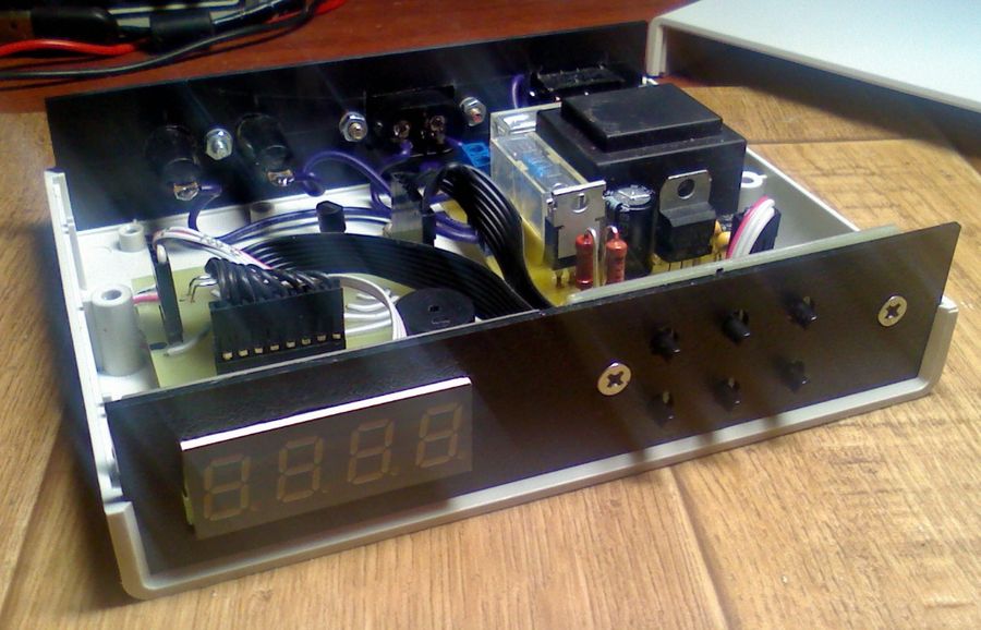
Timer in the case.
Power section.
Boards and connections.
When there are 3 seconds left before the end of the time, the "buzzer" turns on until the end of the time. At the end of the time, the load is turned off, the time on the timer is set to the one that was set at the beginning with the buttons.
For work I use a film negative photoresist. Negative, which means that the template for its exposure must be printed in negative, that is, the places where the tracks will be should be transparent, and where there should not be tracks (foil), toner is applied. If you use a positive photoresist, then naturally the photomask will need to be printed in positive.
They say that you can greatly improve the quality of such boards if you print two templates on a film on a laser printer, then cut them out and combine them (that is, make one out of two).
You can also print a drawing of the board with a laser printer on plain paper. The thinner the paper, the better. Further, to increase the contrast (if it is not sufficient), immerse it in a can of solvent (for example, an automobile 647) for a split second. Let it dry, and then soak it with sunflower oil to make it transparent to ultraviolet radiation, though I have not tried that.
There is no point in repeating how all this is done, since this process is described on dozens of sites. Just type in the search engine "manufacturing of PP using a photoresist", and you will have a bunch of options, after reading a couple of them, you will have an option that is right for you.
We apply the template to the board. As a rule, the template fits tightly to the board. And put it on the scanner glass with UV lamps. Highlighting. We remove the exposed workpiece in a dark place and prepare a solution for development, for which I use soda ash (sold in household stores it is used to soften water and costs a penny).
To do this, dissolve a teaspoon of soda with a slide in a liter of water (if the board is large), or a flat spoon in 0.5 liter of water.
We take our board from a dark place, remove the upper protective film from the photoresist and put it in our solution with diluted soda and wait for about 30 seconds. Then we take a brush and start driving it across our board in order to speed up the process of washing off the photoresist from unnecessary plots. Where the photoresist has washed off, the copper surface is light and shiny. After all the unnecessary photoresist has been washed off, take the board out of the soda solution and rinse it under running water.
A printed circuit board prepared for etching.