Schemes of antenna amplifier range. Simple antenna amplifier. Production of antenna amplifier
We make a frame active antenna for simple shortwave radio receivers.
Is there an opportunity to listen to the ether to people who have no room to install large, full-size antennas? One of the outputs is a frame active antenna installed right on the table, near the radio.
On the practical manufacture of a similar antenna and will be told in this article ...
So, a small-sized frame active antenna, it is an antenna consisting of one or more turns of the copper wire (tube) or even a coaxial cable. The network has abuse examples of such antennas.
I made my antenna in the form of a vertical design, which is installed on the table near the radio. The frame active antenna is a solid inductance coil, made of a copper wire with a diameter of 1.2 mm and contains four turns. Number of turns chosen by NAVAUM)). The diameter of the manufactured frame antenna is approximately 23 cm:

To reduce its own tank, the antenna is wound with 10 mm increments. To maintain the constancy of the step of winding, as well as to give the entire design, the intermediate struts made from the glassstolite with a thickness of 2 mm are used. Sketch spacer is provided below: 
So the intermediate strut in the antenna looks like:

To give stability, all this design applied support racks, also made of fiberglass, and which serve as an antenna legs: 
The copper wire is based on the appropriate holes for struts and racks, and is fixed in them with a droplet of cyanacrylate glue.
This is what the rack is in the manufactured antenna instance:

General view of the manufactured antenna:

For the sake of interest, a manufactured frame antenna was connected to the AA-54 antenna analyzer.
Antenna's own resonance was discovered at a frequency of 14.4 MHz.
The photo below the AA-54 antenna display at the time of measuring the parameters of the frame antenna at the resonance frequency:

As we see, the impedance of the antenna at a frequency of 14.4 MHz is 13.5 ohms, the active resistance-7.3 Ohm, the reactive resistance is relatively small-minus 11.4 Ohm and is capacitive.
The inductance of the framework antenna (and in fact, and is an inductor of inductance) amounted to 7.2 μH.
This is all related to the manufacture and parameters of the actual framework antenna.
But, since the antenna is active, it means its composition also has an antenna amplifier.
When choosing an antenna amplifier diagram, it was guided by the principle of picking up anything too awesome and complicated, and easy to manufacture.
Google, as always, drooped the mountain of schemes)) Without how long thinking, chose one of them, which seemed interesting to me.
The diagram of this antenna amplifier was published somewhere in the early 2000s in one of the foreign journals. This amplifier seemed interesting to me from the point of view that it has a symmetrical input-just suitable for my frame antenna.
Circuit diagram of an antenna amplifier:

In the original, the BF series transistors are used in this amplifier - something like BF4 **.
There was no such thing, so I collected an amplifier from what was at hand-2N3904, 2N3906, S9013.
Actually, the amplifying cascade is collected on the VT1VT2 transistors. On the VT3 transistor, an emitter repeater is collected to match the high output resistance of the amplifier with a relatively low input resistance of the radio receivers.
The amplifier is powered by a voltage of 6 V. Modes of operation of transistors are set by the selection of the resistor R3. Voltages on the transistors electrodes are indicated in the diagram.
The amplifier earned almost immediately. I tried to establish the CT315 transistors in this amplifier, CT361-but the efficiency of work was immediately worsened, therefore it refused this option. An antenna amplifier I collected on the circuit board, but, prepared and pCB for him:

As a receiver for attentive tests of the active frame antenna with an amplifier was chosen
By connecting the antenna amplifier output to the receiver input and turning on the power, immediately noted the noise level increase. This is not an amazing antenna amplifier contributes ...
The last stage of the test was connecting the actual frame antenna to the input of the antenna amplifier and try to accept any signals from the air ..
And it succeeded! Many stations of working with single-band modulation on the range of 40 m are well heard. It is clear that the stations are not heard as loud as a full-size antenna. And it is impossible to compare the normal antenna with a frame antenna located near the receiver. Also, when operating an active framework antenna, there is a slightly elevated level of noise. With this you need to put up - this is a fee for small-sized. It is also desirable to place such an antenna away from all sorts of sources of interference, energy-saving light bulbs, network equipment, etc.
conclusions: Such antenna is quite the right to life, there are quite a lot of stations. For those who have no opportunity to hang a big, long antenna, it can be a way out of the situation.
Video Demonstration Framework active antenna on the range of 7 MHz:
Paris?! Breaking!
Washington?! Breaking!
And after you climbed there, the receiver stopped taking remote radio stations, "the father told me back in childhood.
Since then, several decades have passed, and the receiver, no matter how it happens, continues to take cities. Honestly, I did nothing with the receiver. These Soviet lamp aggregates will work after the apocalypse. Just all the case in the antenna.
Late in the evening, in the reflections of the fireplace of the fireplace, not including electricity, I press the key of the old lamp radio, the glowing scale with cities cooled comforted the twilight of the room, rotating the venier, while setting up on the radio station.
The long-wave range is silent. True, exactly in the rectangle of the glowing window of the city of Warsaw at a frequency of about 1300 meters was taken by a radio station "Polish radio", and this is a distance of more than 1150 km.
Medium waves take local and remote radio stations. And here they take a distance of more than 2000 km.
For almost 2 years in Moscow and the region on these waves (DV, SV), central broadcasting channels stopped work.
Especially alive short waves, here is a full all-wheelhag. On short waves, radio waves are able to get around the Earth and the radio station really take from any point of the globe, but the conditions for the propagation of radio waves depend on the time and state of the ionosphere from which they are capable of reflected.
I turn on the desktop lamp and on all ranges (except VHIs) instead of radio stations solid noise, passing into the rokot. Now table lamp, including network wires - interference transmitter, which interferes with a normal radio. Fashionable, currently, energy-saving lamps and others appliances (Televisions, computers) turned the network wires in the antenna of interference transmitters. It was worth only the network wire from the lamp to move as a couple of meters from the wire decline to the antenna, as the reception of radio stations resumed.
The problem of noise immunity was in the last century, and in the range of meter waves it was solved by various designs of the antennas, which were also called as "antishum".
Antishum antennas.
The description of the antisheum antennas for the first time I read in the magazine "Radifront" for 1938 (23, 24).
 |
| Fig. 2. |
 |
| Fig. 3. |
A similar description of the design of the antishum antenna in the RadiFront magazine for 1939 (06). But here good results turned out in the range of long waves. The amount of noise attenuation was 60 dB. This article may be of interest to Amateur Radiocommunication for DV (136 kHz).
True, currently the best results are obtained using the matching amplifier directly in the antenna, which coax cable Connected to a matching amplifier at the input of the receiver itself.
Antenna sweptwork.
It was my first homemade antenna, which I did for a detector receiver. The first antenna, which I kicked, serving every posting, strictly according to the drawing with the help of the transportation, exposing the corners of the sponge of the twigs. As I did not try, but the detector receiver did not work with her. Put the then instead of the pancake, the cover from the saucepan, the effect would be similar. Then, in childhood, a network wiring receiver saved, one wire of which was connected through the separator capacitor to the input of the detector. But then I realized that for the normal operation of the receiver, the length of the antenna wire should be at least 20 meters, and all sorts of electronic clouds, conductive layers of air over a mellow, let them remain in theory. Old-timers will still remember that the sweater attached to the chimney is extremely well caught when smoke walked vertically up. In the villages, the oven was usually treated in the evening and in cast irons prepared dinner. By evening, as a rule, the wind subsides, and goes the smoke. At the same time, in the evening there is a refraction of waves from an ionized layer of the surface of the earth and the reception in these wave ranges is improved.
The best results can be obtained with the pictures below the antennas (Fig. 5 - 6). These are also antennas with a concentrated capacity. Here, the wire frame and spiral includes 15-20 meters of wire. If the roof is high enough and not made of metal and freely skipping radio waves, then such compositions (Fig. 5, 6) can be placed in the attic.
 |
| Fig. 5. "Radio to all" 1929 № 11 |
 |
| Fig. 6. "Radio to all" 1929 № 11 |
Hall antenna.
I used the usual construction roulette with a length of steel canvase 5 meters. Such a roulette is very convenient as an antenna of a range of range, as it has a metal clips, electrically connected through the shaft with a web ribbon. Pocket receivers with a range of kV have a purely symbolic pin antenna, otherwise they would not fit in his pocket. It was worth only to fix the tape measure on the tape antenna of the receiver, as short-wave ranges in the region of 13 meters began to roam from a large number of radio stations received.
Reception to the lighting network.
This is the name of the article in the magazine "Radio Affection" for 1924 No. 03. Now these antennas have become in history, but if necessary, network wires can still be used in some notched village, having previously disabling all modern household appliances.Homemade g - shaped antenna.
These antennas are presented in Figure 4. A, b). The horizontal part of the antenna should not exceed 20 meters, usually recommend 8 to 12 meters. The distance from the ground is at least 10 meters. A further increase in the height of the antenna suspension leads to an increase in atmospheric interference.
I made this antenna from the network carrying on the reel. Such an antenna (Fig. 8) is very easy to deploy in the field. By the way, the detector receiver worked well with her. In the figure, where the detector receiver is depicted, from one network reel (2) is made an oscillating circuit, and the second network extension cord (1) is used as a g-shaped antenna.
Frame antennas.
The antenna can be made in the form of a frame form, and is an input tunable oscillatory contour, which has directed properties, which significantly weakens interference with the radio.Magnetic antenna.
With its manufacture, a ferrite cylindrical rod is used, as well as a rectangular rod, occupying less space in a pocket radio. On the rod is placed input rebuilt circuit. The advantage of magnetic antennas is small dimensions, and the high quality of the circuit, and, as a result, high selectivity (detuning from neighboring stations), which, together with the directional property of the antenna, only add one more advantage, such as the best noise immunity of reception in the city. The use of magnetic antennas is more intended for the reception of local broadcasting stations, however, the high sensitivity of modern receivers of DV, SV and KV ranges and the above positive properties of the antenna provide a good radiation range.
So, for example, I was able to catch a remote radio station on a magnetic antenna, but it was worth only to connect an additional bulky outer antenna, as the station was lost in the noise of atmospheric interference.
 |
| The magnetic antenna in the stationary receiver has a rotary device. |
On a flat ferrite (similar to the length of the cylindrical) rod measuring 3 x 20 x 115 mm, the coils of the PELSHO brand, PAL 0.1 - 0.14, 190 and 65 turns are wedged on the movable paper frame.
For the range of the range, the contour coil is placed on a dielectric frame with a thickness of 1.5 - 2 mm and contains 6 turns wound with a step (with a distance between the turns) with a loop length of 10 mm. Wire diameter 0.3 - 0.4 mm. The frame with the turns is attached at the very end of the rod.
County antennas.
For a long time I use a attic for television and radio antennas. Here, in gave from the electrical wiring, the antenna of St. and KV ranges works well. The roof of a soft roof, ondulin, slate is transparent for radio waves. In the magazine "Radio to all" for 1927 (04) a year is given a description of such antennas. Author S. N. Bronstein Articles "Ceumary antennas" recommends: "The form may be the most diverse, depending on the size of the room. total length Wiring should be at least 40 - 50 meters. The material is an antenna rope or ringing wire, strengthened on insulators. The thunder switch with such an antenna disappears. "
I used the wire both single-core and stranded from the wiring, without removing the isolation from it.
Ceiling antenna.
This is the same antenna on which the father's receiver took the cities. The copper motor wire with a diameter of 0.5 - 0.7 mm was wound on the pencil, and then stretched under the ceiling of the room. There was a brick house and a high floor, and the receiver worked perfectly, and when they moved to a house from reinforced concrete, then the reinforcement grid of the house became an obstacle for radio waves, and the radio stopped working normally.
From the history of the antennas.
Returning to the past, I was interested to know how the first antenna in the world looked like.
The first antenna was proposed by A. S. Popov in 1895, was a long thin wire, elevated with balloons. It was attached to the slope (receiver, registering thunderstorms), the prototype of the radio telegraph. And during the world's first radio broadcasting in the meeting of the Russian Physico-Chemical Society in the Physics Cabinet of the St. Petersburg University from the first broadcast radio, the thin wire was stretched to the vertical antenna (Radio magazine 1946 04 05 "First Antenna").
 |
| Fig. 13. First antenna. |
The more I know the modern element base, the more I am surprised at how just now electronic deviceswhich previously could only dream. For example, an antenna amplifier, which will be discussed, has a working frequency range from 50 MHz to 4000 MHz. Yes, almost 4 GHz! In the time of my youth, it was easy to dream, and now even a novice amplifier can collect such an amplifier on one tiny chip. Moreover, not having experience with over high-frequency scheme engineering.
The antenna amplifier presented below is extremely easy to manufacture. Has a good gain coefficient low level Noise and low consumption current. Plus a very wide range of work. Yes, there is also a miniature size, thanks to which it can be embedded anywhere.
Where can I apply a universal antenna amplifier?
Yes, almost anywhere in a wide range of 50 MHz - 4000 MHz.- - As a signal amplifier television antenna For receiving both digital and analog channels.
- - As an antenna amplifier for the FM receiver.
- - Dr.
Characteristics of antenna amplifier
- Operating range: 50 MHz - 4000 MHz.
- Strengthening: 22.8 dB - 144 MHz, 20.5 dB - 432 MHz, 12.1 dB - 1296 MHz.
- Noise coefficient: 0.6 dB - 144 MHz, 0.65 dB - 432 MHz, 0.8 dB - 1296 MHz.
- Current consumption of about 25 mA.
The low-noise amplifier has proven itself perfectly. Low consumption current justifies itself.
Also the chip perfectly withstands high-frequency overload without loss of characteristics.
Production of antenna amplifier
Scheme
The scheme uses the RFMD SPF5043Z microcircuit, which can be bought on -.In fact, the whole scheme is a chip amplifier and a filter for its power.
Board amplifier

The fee can be made of foil textolite, even without etching, as I did.
We take two sided foil textolite and drink a rectangle for about 15x20 mm.

Then, a permanent marker draw a layout on the line.


And then you want to poke, and you want to cut the tracks mechanically.

Next, we all brings a soldering iron and solder SMD elements of the size 0603. The bottom side of the foil fee closer to the general wire, thereby shielding the substrate.


Setting and testing
The tincture is not required, you can of course measure the input voltage, which must be within 3.3 V and the current consumed is approximately 25 mA. Also, if you work in the range above 1 GHz, it may be necessary to coordinate the input circuit, a reduction in the capacitor to 9 PF.Connect the board to the antenna. Check showed good strengthening and low noise.

It will be very good if you place a fee in the shielded case, such as this.

You can buy a fee of the ready-made amplifier on, but it is also more expensive than the chip separately. So it is better to freeze as it seems to me.

Supplement scheme
For the power of the circuit, the voltage is required 3.3 V. This is not entirely convenient, for example, if you use an amplifier in a car with a voltage of the on-board network 12 V.
For these purposes, you can enter the stabilizer in the scheme.
Connecting the amplifier to the antenna
By location, the amplifier should be placed in the immediate vicinity of the antenna.To protect against statics and thunderstorms, it is desirable that the antenna would be closed by dCThat is, you need to use a loop or frame vibrator. Antenna of type "" will be an excellent option.
To increase the sensitivity of radio receivers - radio receivers, televisions use various high frequency amplifiers (UHF). Enabled between the receiving antenna and the input of a radio or television receptionist, such an UHF increase the signal coming from the antenna (antenna amplifiers). The use of such amplifiers allows you to increase the radius of a confident radio, in the case of receivers in the composition of transceivers (radio stations), allows you to increase the range of work, or while maintaining the same range to reduce the radiation power radiation power.
In fig. 1 shows a scheme of broadband UHF on one transistor included according to a circuit with a common emitter (OE). Depending on the used transistor this scheme It can be successfully used to frequencies in hundreds of megahertz. The values \u200b\u200bof the elements used depend on the frequencies (lower and upper) of the radio view.
Transistor cascades included in a circuit with a common emitter (OE) provide a relatively high amplification, but their frequency properties are relatively low.
Transistor cascades with a common base (OB) have less amplification than transistor with OE, but their frequency properties are better. This allows the use of the same transistors as in the schemes with OE, but at higher frequencies.
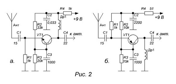
- The L1 coil - the frameless Ø4 mm contains 2.5 turns of the wire PEV-2 with a diameter of 0.8 mm.
- Throttle L2 - RF choke 25 μH.
- Choke L3 - RF choke 100 μH.
- Transistors Kt3101, kt3115, kt3132 ...
Installation of the amplifier is performed on a double-sided fiberglass attachment, the length of the conductors and the area of \u200b\u200bcontact pads must be minimal. When repeating the scheme, it is necessary to provide careful shielding of the device.
If you like the publication, share with your friends in compulsions below ...