Battery Charger Interscol 12 Volt. Charger for an intercol screwdriver. Analog devices with built-in power supply
At the end of last year, I published a couple of reviews on the rework of the batteries of the screwdrivers. Today I will tell about alternative version The charged battery charge using a finished charger.
In general, as always, inspection, disassembly, diagrams, tests.
Last time I offered to use the old charger to charge with a separate converter board. The option is generally not bad, but I began to ask questions, and what to do if the old charger is broken, feast, ate a cat.
And so I accidentally stumbled upon one of the stores on the charger option, which is suitable for 3S batteries, i.e. 12.6 volts. Since this option is one of the most common in the redistribution of old screwdrivers, I decided to book it for review.
The packaging is very ascetic, however, as the inscription indicating the voltage and the charge current. 
The package is very simple, cable and actually charger.
The cable in principle is not bad, that's just the plug tumbled, options - cut, change or search for an adapter. 
The charger is made in the power supply format, quite sweaty, the case is durable. 
On one of the ends of the case there is a two-contact network connector, on the second side of the cable with the usual 5.5 / 2.1mm plug. Cable length is about 1 meter. 
Since this is the charger, and not the power supply that you charge your smartphone / tablet, then there is a charge end indicator. It is true, it is not very bright, with a bright sun, it will not be noticeable, such as in the light of the outbreak.
There is a sticker with an indication of the characteristics, nothing new, besides what was indicated on the package, I did not see. 
As I wrote above, the body is rather durable, but he could not resist the hammer and knife, and there are no other ways to disassemble this product. 
The board inside sits very hard. Partially on bilateral scotch, partially glued with silicone in the area of \u200b\u200bpower elements. The photo shows the insides of the case, in addition, there is some kind of adhesive mass. 
The view is economical, but quite well. Radiators are insulated and held due to the power element itself, an additional petal and silicone sealant.
Also, a transformer and an input throttle are glued to the housing. In general, the fee was taken pretty hard. 
The input is a fuse, as well as the input filter. Unfortunately there is no thermistor, instead the jumper. 
1. The input capacitor has a capacity of 68MKF, for the power of about 40 watts is quite enough.
2. CS7N60F high-voltage transistor in a fully isolated case.
3, 4. On the one hand, the transformer hid opt feedback, On the other hand, the right interference Condenser y class, so it will not kill you.
5. Output diode assembly 10 amp 100 volts, with a reserve both by current and voltage.
6. Output capacitors have a capacity of 1000mkf and voltage up to 25 volts, there are also no questions here. Along the way, there is a place to install an interference throttle and a third capacitor. 
The bottom of the component board is even more. 
"Hot" side of the power supply. Here I also did not have any questions, well, it almost did not arise :) 
"Cold" side. Here are elements of stabilization of voltage, current, as well as indication of the end of the charge. 
The claim to the "hot" side was only in terms of soldering, or rather its quality. It seems that the PWM controller was turned out, since the remaining components are breed neat.
There is no questions to the output side, everything neatly, the elements are additionally fixed using glue. Operational amplifier LM358. 
Since review similar device I still have no, it was impossible not to redraw the scheme.
However, the primary part of the power supply turned out to be almost one to one with the power supply, which I have already overlooked. The block is very reliable and high-quality.
The difference only in the nominal numbers of some components, as well as their number, the chip has the same pinout. 
Since the scheme is large, then it is more clear, I broke it into two parts, primary and secondary.
The secondary side differs from the usual diagrams of power units, as it contains more nodes. 
Sick separately nodes.
1. Green - the output voltage stabilization node that is responsible for CV mode.
2. Red - current stabilization, SS mode.
3. Blue - indication node.
Left at the top two rectifier, main and optional (D3, C5) for food operational amplifier and LED. Additional nutrition It is necessary that these items do not consume a current when the battery is connected, and the charger is not included in the outlet.
Between the red and blue node, the reference voltage source for the indication node and current stabilization. 
And although mostly everything is done quite correctly, but there is a feature. In parallel, the first condenser is connected to the resistor with a face value 2.2k (R13A), therefore consumption in the off state is still. You can try to fix this situation by installing a diode (marked in red) instead of a jumper, which in its queues stands on the site of the missing interference choke. But there is a problem, this diode will warm up, and noticeably, because I would recommend to leave as it is.
Now what to change if you need another voltage / current.
1. Green - divider according to the voltage measurement circuit, an increase in the upper resistor rating will increase the output voltage, lower - reduce.
2. Blue - an increase in the nominal shunt will reduce the current, a decrease - increase. The change will be proportional to the change in the nominal. Also, the change in this resistor affects the indication.
R19, \u200b\u200bR13, an increase in the upper resistor is to reduce the output current, the change in the lower acts on the contrary.
3. Orange - Disload the indication threshold. All the same as in paragraph 2, only for indication. By the way, I note that this node has a hysteresis, because the red / green switch occurs jumps like, and not smoothly, a trifle, but nice. 
Separately, a photo for perfectionists, here I listed what can be installed on the fee.
1. Y- condensers, since the connection without grounding, then the meaning does not have. If you replace the slot to threekone, reduce interference with the network.
2. The thermistor will reduce the starting current. For example NTC 5D-9
3. Output choke. Reduce the level of pulsations at the output, current more than 3 amps, inductance 1-10mkg.
4. The varistor will increase the power supply protection when the high voltage is applied to the input. Diameter 10mm, voltage 470 volts.
5. X-capacitor, reduce the level of interference in the network, place under 22-33NF.
6. Two-winding choke, usually on a small ring, also to reduce interference in the network.
7. Diode assembly. You can put in parallel first, it will slightly increase the efficiency and raise reliability, it is better to put the same as already used, 10 amp 100 volts.
8. Output capacitor. At the level of the pulsations will make little, but can raise the reliability of work. 1000mkp 25 volts. 
Go to tests.
To begin with, I will go through the main positions
1. The output voltage is overshadowed by about 30mV, I think that it is quite normal.
2. Current from the battery when the power is turned off, about 7mA. Pretty much, discharge the battery in about 2-3 weeks. It is better to use batteries with protection, however, protection is mandatory anyway.
3. Charging current 2.9 amps, slightly lower than the stated, but I believe that nothing terrible.
4. The display is set to a current of 270mA, when the charge current drops below this value, the green LED is turned on and the red rises.
5, 6. Since the device does not know how to completely de-energize the battery, then you will see the current drop in almost zero. For example, from 66th to 28m, the current fell about 8 minutes.
The mode without complete current removal is permissible, although not very desirable. If the battery is working, then there will be no problems, but I would advise just not to leave it for a great time, such as a day or two. 
Then I connected the charger to the electronic load. But since the electronic load does not have CV mode, then the current stabilization circuit has had to be connected.
The load current in 3 amps was set and the body for thermocheating was closed. Along the way, the care of stress was controlled, there are also no problems here, 5mV after an hour of thermoproat, it simply excellent, it affects the most part applied accurate resistors. 
Since this is a charger, and not a power supply and most of the time it works with a maximum current, then I immediately assign a current of 3 amps. The test time was 1 hour, during this time it fully charged the battery with a capacity of 2400-2600mach. Further, in any case, the current will start falling and testing the heating is not. 
1. An hour later I checked the temperature of the body, in the hottest place the device showed 59 degrees, although the body was not hot, it is possible that the plastic is partially transparent in the IR range.
2. Opened the case and measured the temperature, the highest in the region of the standard and shunt of the primary side, about 80 degrees, the transistor had a temperature of 70-72 degrees.
3. Closed the housing for a couple of minutes, turned 180 degrees so that the remaining components were visible and measured again. This time the output diode assembly had the highest temperature, about 85 degrees.
From the tests I can conclude that everything is fine with the temperature regime, there is a stock of about 20-30 degrees to critical temperatures. 
After the review, a video was shot, where I briefly explain what I was just like an addition.
What can be said as a summary, first on points:
Benefits
Strong and neat design
Components are applied with a margin
Good stability of parameters
No overheating
Clear work of the charge indication
disadvantages
Lack of full charge shutdown
Own consumption in 7th.
Cable plug has flat pins.
My opinion. In my opinion, the device has only one significant disadvantage, it does not remove the charging current completely. The correct charge goes until the current is reduced below 1/10 from the installed, then disconnect and subsequent inclusion if the voltage decreases again. Of course you can think and make some kind of scheme with a hysteresis that will not disconnect the charge, but to reduce the output voltage so that the charging current is stopped. But in my opinion, if you do not leave the connected battery for a long time, it will be completely the option as done now.
I was pleased with a pretty good assembly and the fact that the components are installed with a margin. It is also worth noting the absence of overheating than a rather large number of power supplies. I generally seemed to me that the device was assembled on the basis of 12 volts 5 amps, raising a little tension and lowered the current, therefore it turned out such a result.
In general, if you have converted the batteries of your screwdriver and they have a voltage of 12.6 volts (three consecutive batteries), and the native charger is not subject to restoration, then a pretty good option.
At the time of order, the charger was worth about 13.7 dollars, for review, the manager reduced the price of up to $ 11, which in my opinion it is quite adequate for this device Taking into account its functionality and assembly quality.
That's all, I hope that the review was useful.
Small bonus
And do not test the battery of the smartphone. 
The goods are provided for writing a survey shop. The review is published in accordance with paragraph 18 of the site rules.
I plan to buy +52. Add to favourites I liked the review +79 +144
In the previous article, I considered the issue of replacing nickel-cadmium (nickel-manganese) NISD (NIMN) accumulators of a lithium screwdriver. It is necessary to consider several rules for charging batteries.
Lithium ionic batteries size 18650 are mainly charged to a voltage of 4.20V per cell with a permissible deviation no more than 50 mV because the increase in voltage can damage the battery structure. The battery charge current can be 0.1xc to 1xc (here C-capacity). It is better to choose this value by datashet. I applied the accumulators of the brand in the alteration of the screwdriver. We look at the datashet-current charging -1,5A.

The most correct will be charged lithium batteries Two receptions according to the CCCV method (constant current, constant voltage).
The first stage should provide a permanent charge current. The value of the current is 0.2-0.5c. I applied a battery with a capacity of 3000 m / h, then rated current The charge will be 600-1500m. After charging, the banks goes on the unchanged voltage, the current is constantly decreasing.
The voltage on the battery is maintained in the range of 4.15-4.25. The battery charged if the current decreases to 0.05-0.01c. Taking into account the above we use e-cards with Aliexpress. The reduced CC / CV board with current limit on the XL4015E1 chip or on LM2596. It is preferable to pay as it is more convenient in the settings.
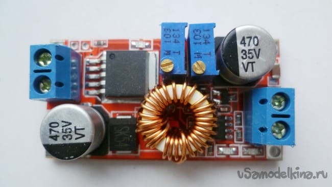

Characteristics XL4015E1.
Maximum output current up to 5 A.
Output voltage: 0.8 V-30 V.
Inlet voltage 5 V-32 V.
has similar parameters, only a current to 3 A.
List of tools and materials.
Adapter 220 \\ 12 V, 3 A -1St;
-state screwdriver charger (or power supply);
- payment charge CC / CV on or on -1pcs;
-Contentory wires -Passer;
-tester;
-PlastMass box for charge fee -1pcs;
-1ct minivoltmeter;
- transmitted resistor (potentiometer) for 10-20 com -1pcs;
- Power supply for the battery compartment of the screwdriver -1pc.
Step one. Assembly of the batteries of the screwdriver on the adapter.
CCCV fee We have already chosen above. You can apply any parameters to the power supply to the power supply voltage not lower than 18 V (for the 4S circuit), the current 3 A. In the first example of the manufacturer of the charger for lithium-ion accumulators of the screwdriver, I used the adapter 12 V, 3 A.

Previously I checked what current it can issue a feast with a nominal load. I connected to the autolampu and walked half an hour. It gives out free without overload 1.9 A. also measured the temperature on the transistor-40 ° C radiator. Quite normal mode.

But in this case there is not enough voltage. It is easy to be corrected, with the help of just one penny radio metal resistor (potentiometer) by 10-20 com. Consider model schema adapter.


The diagram has a controlled TL431 stabilitron, it is in the feedback circuit. His task to maintain a stable output voltage in accordance with the load. Through a divider of two resistors, it is connected to the positive output of the adapter. We need to roll to the resistor (or drop it at all and in its place to solder, then the voltage will be adjusted and at a smaller direction) which is connected to the output 1 of the TL431 stabilion and to the minus tire variable resistor. Rotate the axis of the potentiometer and exhibit the desired voltage. In my case, I set 18 V (a small supply of 16.8 V to fall on the CC / CV board). If you have the voltage indicated on the housings of electrolytic capacitors standing at the output of the circuit will be greater than the new voltage they can explode. Then it is necessary to replace them with a reserve of 30% by voltage.
Next, connect to the adapter fee for controlling charge. I exhibit a stress resistor with a voltage of 16.8 V. Another trimming resistor set a current of 1.5 A, pre-connect the tester in the ammeter mode to the output of the board. Now you can connect the lithium-ion assembly of the screwdriver. Charging went fine, the current by the end of the charge fell to a minimum, the battery charged. The temperature on the adapter was in the range of 40-43 ° C, which is quite normal. In the future, it is possible in the enclosure of the adapter to improve ventilation (especially in the summer) to chop holes.
The end of the battery charge can be seen by turning on the LED on the board on XL4015E1. IN this example I used another fee on LM2596 as accidentally during the experiments burned XL4015E1. I advise you to charge better on the XL4015E1 board.
Step two. Assembling the diagram of the charger of the screwdriver batteries on the regular charger.
I had a regular charger from another screwdriver. It is calculated for charging nickel-manganese batteries. The task was to charge and nickel-manganese batteries and lithium-ion.


It decided to simply sucked to the weekend (red plus, black minus) wires to CC / CV card.
The idling voltage at the exit of the regular charger was 27 V, it is quite suitable for our charging board. Further all the same as an option with an adapter.
Wireless tools use energy batteries for their work. Naturally, from time to time it is necessary to fill the consumed stock. This process is called charging. In the process of charge and discharge, reversible chemical reactions occur in the battery, which determine the principle of its operation.
Varieties for charging
Performing the same function, chargers have a variety of internal structure options. By type of supply voltage of the household electrical power grid, the design for charging the screwdrivers differ in such:
- Transformer;
- Inverter (impulse).
Transformer devices initially appeared first, because they demanded the simplest electronic base. The classic design of the device includes:
- Transformer;
- Rectifier bridge;
- Filtering capacity;
- Current stabilizer;
- Controlling scheme.
![]()
Regardless of the type of stabilizer and additional options, transformer charging devices combines such a deficiency as large dimensions and weight. This is due to the fact that the mass-size transformer indicators increase in proportion to the power of the product. Accordingly, those chargers that have acceptable mass and dimensions are capable of producing small charging current values, and the charge process goes for a long time.
From the specified shortage of free inverter-type devices that use the input voltage conversion in the high frequency current. This approach allows you to use small-sized transformers working with large power values. With dimensions, significantly smaller than that of transformer structures, inverter can produce a significant largest charging current. The battery charge time is reduced to one hour and less.

Additional functions
The simplest charger (memory) does not control the status rechargeable battery. All this is assigned to the user. As a result, a regular underwear, a long charge, a non-optimal charging process, all this leads to a sharp reduction in battery life. This type of circuitry is applied only in the cheapest models of screwdrivers and cannot be recommended for the acquisition.
More expensive models have a built-in charge controller or shutdown timer. Charging the battery is performed until the required capacity of the container is reached or through a certain time. In the latter case, it is possible for a long time, but a long-lasting voltage supply is excluded. The charge level control is conducted in the battery voltage level. Most of the types of tools in the middle price category Use exactly such models.
The most advanced models have a circuit of a charge controller based on the use of a microcontroller. At the same time, in addition to the actual charge, the preliminary discharge of not fully developed elements is applied and to a strictly defined value. This procedure eliminates the appearance of the effect of "memory" characteristic of alkaline batteries, and helps align the capacity of individual battery elements. The battery is charged according to a specific algorithm according to the manufacturer's requirements.
The charge level is controlled by the battery voltage. Delta method is used. It is based on the feature of Ni-Cd and Ni-Mh batteries to a certain decrease in voltage at full charge. The controller circuit responds to a decrease in the voltage at the end of the time period and turns off the charging current.

Charger for a screwdriver on microcontrollers will have high costBut at the same time will significantly extend the service life of an expensive battery and reduce the time of the total charge. This type of charge controllers is in a set of expensive professional models of the screwdrivers.
Charge voltage and form factor
Manufacturers do not have a single standard for the voltage of the tool. On the one hand, the low battery voltage reduces its cost by reducing the number of elements, on the other hand, more high-voltage batteries give a number of advantages:
- More high power devices;
- With the same power reduced current consumed;
- Increases period of work between charges.
The increased number of elements increases the cost of the tool, so this approach is characterized by manufacturers of high-quality and expensive equipment.
Note! If the weight of the tool is important, then preference should be given low-voltage products. 18-volt screwdrivers have the most significant weight. The exception is lithium-ion batteries, but they can only be found in the most expensive models tool.

Since the EMF Ni-Cd and Ni-MH batteries has a strictly defined value, namely 1.2V, that and the battery voltage of elements is reduced to a number of several values:
- 10 batteries - 12.0V;
- 11 batteries - 13.2V;
- 12 batteries - 14.4V;
- 13 batteries - 16.6V;
- 14 batteries - 17.8V.
You can meet other values, as towards the reduction, and in the direction of the increase, but infrequently.
To simplify, many manufacturers indicate a rounded battery voltage value. For example, the battery with the 14th elements often has the designation 18 volts, and from the 10th – 12 volts.
Rechargeable screwdriver batteries differ not only by voltage, but also on the form of fasteners and location of the terminals. From this it follows an important conclusion.
Important! Various batteries and devices for charging them are not compatible with each other. The exception is the products of one manufacturer, which were created taking into account compatibility.
Modernization of chargers
The alteration of regular chargers for a screwdriver is usually made in order to improve their characteristics. The most simply averted conversion of the transformer type, which changes only the control and control circuit. Inverter change is much more complicated. In most cases, revision requires a complete replacement of the internal "filling" of the device.
As a rule, alterations are exposed charging blocks lower price category. The main options that are entered into the conveyed design, – this charge level control and automatic shutdown. Alterations of this type made using analog schema engineering are not particularly difficult and accessible to a novice and medium radio amateur.

Making more complex structures, with control on a microcontroller, for only experienced masters, besides, do not have a special meaning. As already mentioned, the simplest devices are produced for cheap tool models, respectively, and the quality of batteries in them is not at the height. Winning in the reliability of batteries, the extension of their life life will result in disproportionate costs for such a remake of the charger.
Repairs
Just as the alteration, the repair of the charger for the screwdriver requires certain knowledge in the field of radio engineering. Without experience, you can replace the power cords and fuses. It is worth noting that such malfunctions occupy one of the main places in frequency. The lack of charge and power indication are usually associated with a breakdown of wires or fuse burning. Both faults are detected by calling with an ohmmeter.
More serious repair of the charging of the screwdriver, especially in expensive structures, is difficult to be lacking concept.
Important! An independent or unqualified repair of chargers for lithium-ion batteries is fraught with ignition and even a battery explosion, since the batteries of this type are extremely sensitive to the charging mode.
Video
The rechargeable screwdriver is an alternative to ordinary scolding when performing both small tasks and large repair projects in the house. The tool is available for the price, they are easy to use, and a special advantage is the lack of wire, usual for power tools. For periodic recharging batteries, a charger is used for a screwdriver.
Advantages of battery tools
Today there are many devices that successfully cope with the installation work using fasteners: dumping, drills, drilling machines, many of them have a charger for a screwdriver.
Small, lungs, mobile and autonomous screws have advantages:
Wireless power supply device
Sometimes for old tool models it is impossible to purchase a new charger and need to refine or make a new one. For lead-acid batteries Ni-CD and Li-Ion, a charching diagram for 18 volts screwdriver will be required. The main features of this universal source are:
- Voltage direct current.
- Automatic shutdown with full charge.
- Maximum current 5 amps, batteries can be charged as usual.
- Fully customizable mode according to battery specifications.
- Low cost.
- Optimal electrical power. No special details are required, all of them are standard and easily accessible.
- LED indicators to monitor the condition of the cut-off and charging.
- Suitable for garages and home use.
This multipurpose device is a source of constant voltage by 5 amps, however, for charging a smaller current, an additional DC circuit may be required between the input power supply.
With deep charging, the battery may overheat, which should be protected by an automatic temperature controller circuit or fan cooling. List of parts for repairing screwdriver with their own hands:
- Resistors.
- Capacitors.
- Simistras.
- Stabilians.
- Reducer.
Repair of current sources
The batteries actually do not have complex spare parts, as it is assembled from the simplest charging elements. In order to determine the repair, you need to open the source and check the availability of damage. Tools and materials that will be needed when repairing:
- Multimeter.
- Screwdriver.
- Electric contact cleaner.
- Insulating tape.
There are cases when the coil of the wireless turning has a defect and, therefore, overheats the device. Isolation easily melts, batteries fail and the wireless screwdriver cannot be used. Technical error You can not always determine the external inspection and need a disassembly of the tool.
Sequence of operations:
Diagnostics of power tools
Hot surfaces of the wireless screwdriver and batteries indicate overheating tool. Overheating is a process that can occur in two cases. On the one hand, the screwdriver has an internal defect, and on the other hand, it is possible that it is used incorrectly. To do this, before repairing you need to check:

Screwdrivers produces a large number of firms, the tools of firms in Interskol, Bosch, Makita are particularly popular. They are usually extremely durable and reliable, nevertheless, individual parts can wear out. For example, when the drill does not work when naught on the trigger. Such a breakdown says that the trigger does not work (button). Replacing the trigger is a fairly simple operation. Before repairing the repair, the battery must be removed to prevent injury to prevent the engine trigger mechanism. The procedure for replacing the regulator on the example of a charger for the Bosch screwdriver:

Another type of repair is renovated by Bosch, for example, or from another well-known manufacturer, it takes much less often and better entrust it to the service center.
Rechargeable screwdrivers These days are quite reliable, so it is generally difficult to find cases of breakdowns of a model with a voltage of 18 V. Lithium-ion batteries Have a great time autonomous work and low speeds The self-discharge, thanks to which the tools equipped with them are constantly being used in the household.
Use, power tools significantly facilitates our work and reduces the assembly time. Currently, self-powered screwdrivers scored great popularity from the battery. Within the framework of this article, consider the scheme of a typical charger for a screwdriver as well as repair tips and options for amateur structures.

The power portion of the charpecker is a power transformer of type GS-1415 designed for a power of 25 watts.

A reduced variable voltage is removed from the secondary winding of the transformer. It follows from 4 VD1-VD4 diodes type 1N5408, through fusible. Diode bridge. Each semiconductor element 1N5408 is designed for direct current to three amps. The electrolytic C1 container smoothes pulsations appearing in the diagram after a diode bridge.
Management implemented on microsite HCF4060BE.which combines a 14-bit counter with the components of the specifying generator. It controls the type S9012. It is loaded on the S3-12A relay. Thus, a circuitry is implemented by a timer, including a relay for the battery charge for about an hour. When you turn on and connect the battery, the relays are located in a normally open position. HCF4060BE gets meals through 1N4742A by 12 volts, because from the output of the rectifier goes about 24 volts.
When the "Start" button is closed, the voltage from the rectifier begins to follow the stabilion through the resistance R6, then the stabilized voltage goes to 16 output U1. Opened transistor S9012, which manages HCF4060BE. The voltage through the open transition transistor S9012 should be on the relay winding. Contacts of the latter are closed, and the battery begins to charge. The protective diode VD8 (1N4007) is shunting the relay and protects the VT from the reverse voltage jump, which will occur at the time of de-energization of the relay winding. VD5 does not allow to discharge the battery when disabled network voltage. With the blurring of the contacts of the button "Start" will not happen. food is coming via VD7 diode (1N4007), VD6 stabilodron and quenching resistor R6. Therefore, the microcircuit will receive power even after the button is released.
Replaceable typical battery From the power tool assembled from separate consecutively connected nickel-cadmium Ni-CD. batteries, each 1.2 volt, that is their 12 pieces. The total voltage of such a battery will be about 14.4 volts. In addition, the temperature sensor is added to the battery package - SA1 it is glued to one of the Ni-CD batteries and fits tightly to it. One of the terminals of the thermostat is connected to a minus battery. The second conclusion is connected to a separate, third connector.
When the "Start" button is pressed, the relay closes its contacts, and the battery charge process begins. The red LED lights up. An hour later, the relay with their contacts tear the chain battery charge chain. The green LED lights up, and the red flies.
The thermocontact tracks the temperature of the battery and breaks the charge chain if the temperature is above 45 °. If this happens earlier than it works, this indicates the presence of the "memory effect".
The basis of the design is the adjustable stabilizer of the positive voltage. It allows you to work with a load current up to 1,5a, which is quite enough to charge batteries.

A variable voltage of 13V, removed from the secondary winding of the transformer, straightens the D3SBA40 diode bridge. At its outlet, there is a filter capacitor C1, which reduces the ripple of the straightened voltage. From the rectifier, the constant voltage enters the integrated stabilizer, the output voltage, which is defined by the resistor R4 at 14.1V (depends on the type of across the screwdriver). The charging current sensor is the resistance R3, parallel to which the trim resistance R2 is connected, the charging current level is set using this resistance, which corresponds to 0.1 from the battery capacity. At the first stage, the battery is charged with a stable current, then when the charging current becomes less than the values \u200b\u200bof the limit current, the battery will be charged lower current to the voltage of the DA1 stabilization.

Charging current sensor for the HL1 LED is VD2. In this case, HL1 will indicate the current with a face value up to 50 milliam. If you use R3 as a current sensor, the LED will go out at a current of 0.6a, which would be too early. The battery would not have done to recharge. This device can also be used for six-speed batteries.