Twisted pair diagnostics. Types of twisted-pair cable damage and how to find them. About connecting a PC to an active network using a twisted pair cable
Been eyeing similar device since in the office, I work as a system administrator (if someone does not know - a system administrator), there is often a problem with a twisted pair cable (they will press the door, then they will tear it out of the connector, etc.). So you have to look for problems.
And this tester in a matter of seconds can determine an open circuit, short circuit, or simply improper crimping of the cable.
So, you can connect cables with connectors to the tester - RJ-45 ( twisted pair), RJ-11 (telephone cable), USB and BNC ( coaxial cable).
Equipment:
1 x Tester
1 x Bag
1 x BNC connector
1 x Instruction 
The device is powered by a battery "crown", which is not included in the kit (for $ 16 they could have put it in the kit).
The tester itself looks like this: 
It has only one button with which the cable is tested, as well as 15 LEDs, which actually serve as indicators.
The tester's connectors look like this: 
One part is separated: 
Downside: 
Battery placement: 
Since the tester was bought mainly to test a twisted pair, therefore I will describe the operation of the device only on a twisted pair, which I will spoil a little (which you will not do for the sake of review), I think when connecting a telephone cable, USB cable and coaxial cable, the principle will be similar.
We connect the cable to the tester only on one side, if the cable has no short circuit, the tester will show " no connection"and the orange LED on the side will light up, the upper LEDs will not light up, the green LED should always be on, showing the battery charge: 
If the cable is OK, the blue LED will show " connected":
Making a cable break: 
And the blue LED also lights up, but the LEDs on top (orange), not all will be on, signaling " break":
Now we do the closure: 
The tester noticed this and reported with a red LED, and orange LEDs show which wires. " close":
Now we will connect the wires, but we will mix up the colors: 
We receive the message " non-parallel", but all the orange LEDs are on (it would be better if they made an indication of the wrong connection): 
The device also emits sound signals:
1 beep - no connection
1 continuous beeping all "ok" (the cable is crimped correctly and there is no short circuit, but a break is not excluded)
2 beeps - the cable is not crimped correctly
3 beeps - somewhere short circuit
Video:
Now let's analyze the tester: 


The brazing is good, but the brazing liquid has not been removed.
Subject to the results:
- It seemed to me that the price is a little overpriced
- It is a pity that it does not display in what place the wrong connection
- No battery
+ Instant display of the result
+ You can connect not only a twisted pair, but a telephone cable, USB cable and coaxial cable
+ Includes a cover (under the skin)
+ Can measure cables up to 100 meters long (more than 100 meters cannot be used at all)
+ Intuitive display of results
+ Sound indication
+ Detachable panel(you can test the cable 100 meters from the tester itself).
Conclusion: I liked the tester, now it will be easy to determine the breakage, poor compression of the cable, as well as a short circuit. If you are not confused by the high price of this tester, you can safely buy it.
IN NO EVENT DO NOT PRESS

P.S. Your " positive»Voices are very important to me, the more voices, the more desire to write new topics (and not only me, but also everyone who writes reviews), thank you for your attention and understanding.
P.P.S. If possible, I am ready to answer any questions.
Thank you for the attention! I plan to buy +20 Add to favourites I liked the review +20 +65
If you need to find a malfunction of equipment or electrical wiring, one of the operations that is performed first of all is to test the cables and wires with a multimeter (tester) to check the serviceability of the circuit (no breaks in it), the presence of a short circuit and determine its resistance (if necessary ). Thus, it is possible to easily and quickly enough check the lamp, iron, switch, fuse, transformer for serviceability. How to ring the wires with a multimeter correctly will be discussed in this article.
What you need to know about the device to ring the wires
If you plan to ring the wiring in an apartment, you need to know a few fundamentally important facts about multimeters. First of all, it is worth noting that you can check the wire with the simplest device. Inexpensive is fine chinese model with minimal features.
But at the same time, it is most convenient to use a device that has the dial function itself. In order to set the handle of the device to the appropriate position, it is necessary to turn it in the direction of the diode icon (as an option, an image of a sound wave can be additionally applied). This means that when checking the continuity of the wire when the contacts are closed, it will sound sound signal.
But the presence of a soundtrack is completely optional for the continuity of the wires with a multimeter. An open circuit will be indicated by a unit on the display indicating that the resistance level between the probes is higher than the measurement limit. If there is no damage in the investigated area, the resistance value will be displayed on the screen, which, ideally, should tend to zero (provided that it works in small household networks).
Sequence of actions when dialing
- Before ringing the circuit with a multimeter, you need to turn the handle of the device to the desired position.
- Install the ends (test leads) into the corresponding sockets. The black wire goes into the socket marked COM (sometimes it can be marked with "*" or the grounding sign), and the red wire goes into the socket where the Ω sign is indicated (sometimes they put the R sign). It should be noted that the Ω sign can be applied both separately and in combination with the designations of other units of measurement (V, mA). This is the correct position of the test leads, which will allow you to maintain polarity during further measurements. Although if only the integrity of the wires is checked, their mutual position will not affect the result obtained.
- Switch on the device. For this, a separate button can be provided or switching on can occur automatically when the knob is turned to the desired position when selecting the measurement limits or operating mode.
- Close the measuring ends together. If a signal sounds, it means that the device is working properly and is ready to work.
- Take the cable or wire under test (its ends must first be stripped of insulation, stripped to a metallic sheen, dirt and oxides removed from the surface). Touch the test leads to the bare sections of the conductor.
- In case of continuity, a beep will sound and the meter reading will either be 0 or indicate the resistance value. If the display shows 1 and there is no beep, it means that the tested conductor is broken.
Safe dialing rules using a multimeter

continuity of the network cable with a multimeter
Working with electricity does not allow unprofessionalism, therefore, there is a certain list of rules that make it possible to make it as accurate, fast and safe as possible.
- It is most convenient to use special tips at the ends of the test leads for continuity, which have received the more common name "crocodiles". They will make the contact stable and free your hands when taking measurements.
- When dialing, always the tested circuit must be previously de-energized (even low-current batteries must be removed). If there are capacitors in the circuit, they must be discharged by shorting. Otherwise, the device will simply burn out during work.
- Before checking the integrity of a long conductor during measurements, it is important not to touch the bare ends with your hands. This is due to the fact that the resulting readings may be incorrect.
When a multi-core cable is ringing, it is necessary to separate and strip all existing cores from both ends. After that, you need to check the circuit for the presence of short circuits: for this, a "crocodile" is fixed on each core in turn, all the rest are touched with the other measuring end in all possible combinations.

We check if there is a short circuit between the cable cores. If the indicator shows "1" and there is no sound signal, then everything is in order, otherwise there is a short circuit.
In this case, the sound signal will mean the presence of a short circuit between the tested cores. This may not be of practical importance for small cross-sectional multicore cables operating in low-current networks, but it is fundamentally important when working with high voltage.

We call the cable cores. There is a sound signal - everything is fine, otherwise the vein is damaged.
To determine the integrity of the cores, the same operation is performed, only at one of the ends of the cable, all stripped cores are twisted together. When searching for a break, it is important to take into account that the absence of a sound signal at any of the ends will indicate a violation of the integrity of the conductor.
We call the wiring in the apartment with a multimeter
Consider, as an example, a modern apartment in which the wiring is carried out in accordance with current requirements and regulations. This means that when laying the lines for lighting and powering the sockets, they were wired, and separate wires were laid for each of the rooms for them. Each of these circuits is powered from the apartment panel through a separate circuit breaker.
If the light has disappeared in one of the rooms, first it is worth checking the serviceability of the lamp. Before starting work, it is necessary to de-energize the room / apartment, depending on the power supply scheme. When using an opaque incandescent lamp in a luminaire, it is difficult to visually determine the integrity of the filament, so a multimeter and its continuity function will be required. Let's figure out step by step how to do it correctly.
First you need to check the flap for the presence of triggered machines. In the first case, they will be in the on position (then the malfunction may be hidden in the room switch, lamp or socket). The likelihood of damage to the wiring in such a situation is small. If the device has worked, it will be necessary to check everything except the room switch, including the switchboard itself.
If the machines did not work
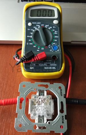
We call the switch. When the switch is on, there should be a sound signal, when it is off - silence and "1" on the indicator.
- Make sure that there is voltage at the input and output of the machine. If it is, you can proceed to further verification.
- Prepare the device for operation and check its serviceability by short-circuiting the measuring ends.
- Unscrew the lamp from the socket.
- With one of the measuring probes touch the base (the metal part of the threaded lamp), and the second touch the central contact of the lamp (the insulated center of the end part of the base).
- A beep and a readout other than 0 or 1 mean that the lamp is working properly. If it is faulty, you need to replace it, which will be the solution to the problem.
- We check the cartridge for serviceability. To do this, you need to disassemble the lamp, make sure that the wires and contacts are intact. If everything is in order, then the cause of the breakdown is not in the cartridge. If faults are found, they must be eliminated. The lamp must not be screwed in yet.
- We check the health of the room switch. To do this, remove the plastic cover, unscrew the screws and take it out of the mounting box. We inspect the equipment for the appearance of carbon deposits, check the tightening of the fasteners. If everything is in order, you need to install the measuring ends of the tester on the contacts of the switch. The appearance of a sound signal when dialing in the on position will indicate that the equipment is in good working order. In this case, the wires do not need to be disconnected.
During such a check, as a rule, a malfunction is revealed, which becomes the cause of all the troubles. Eliminating it allows you to quickly solve the problem.
If the machine is triggered
To ensure electrical safety when carrying out work, in this case, the voltage is turned off using a general apartment machine. Next, the health of the cartridge and the wires connected to the lamp is determined according to the algorithm described above. In the absence of faults, you need to check the wiring itself using a multimeter and a dial function. Such malfunctions occur quite rarely, but still happen, for example, during installation false ceilings or decorative elements of the interior.
In this case, the wiring is dialed in the following way.
- Using a screwdriver, disconnect the supplied conductor (if the installation is done correctly, it is at the bottom) and take it to the side. The "zero" of this group is, as a rule, on the zero clamp under the machines.
- We unscrew the incandescent lamp from the holder. With the help of a tester, ready for operation, we check the line by connecting one of the measuring probes to "zero", and the other to the disconnected conductor. If the device beeps, then the wiring is short-circuited.
- In this case, in the room under the ceiling above the switch, we find and open the junction box. Disconnect the wires.
- We check all groups of wires for a short circuit.
To determine the section of the circuit in which there is a short circuit, we again check the circuit on the apartment panel with a multimeter. If the signal sounds, it means that it is the wire laid from the shield to the box in the room that needs to be repaired. Otherwise, the search will need to continue until the result is obtained.
Video
From all of the above, we can conclude that the presence of a multimeter with a dial function in the house is an objective necessity for any home craftsman. With such a device, in most cases, it will be possible to quickly eliminate minor malfunctions without seeking help from specialists.
The message "Network cable is not connected" appeared in the floating window on the computer monitor, the LED on the network card does not light up. You insert, remove the RJ-45 plug in the hope of a poor contact in the connection and realize that the cable is faulty. If you do not have a separate network card installed in your computer, and the network cable plug is inserted directly into the motherboard, then the LED will not light if the connection is disconnected by software.
Nowadays, a twisted pair network cable is often first connected to a router, which sometimes "freezes". Therefore, the first step is to reboot the router. To do this, it is enough to disconnect it from the mains for a minute and then turn it on again. It is quite possible that Internet access will be restored after that.
Disconnection can occur without your direct participation, for example, due to unstable mains voltage launched by unlicensed programs or a virus. To check in Win XP you need to go to: Start / Settings / Control Panel / Network connections and make sure the connection is connected. Less often, but it also happens, the driver does not work correctly network card... You can check: Start / Settings / Control Panel / System / Hardware / Device Manager / Network cards. There should be no warning signs.
Network cards very rarely fail, this sometimes happens after a severe thunderstorm. You can check the performance of the network card by connecting it to a known working line or by installing it in another computer, without forgetting to install a driver for it. Sometimes it is possible to make the network card work by swapping it into an adjacent slot motherboard.
Call to technical service the provider will help to check the functionality of the line from their side. If everything is in order in the computer and the provider, therefore, the cable is out of order twisted pairs and its repair is required. You can, of course, call specialists and wait, but if you wish, it is possible to carry out diagnostics and repair the twisted-pair cable with your own hands.
The following twisted pair cable faults are most likely:
- complete breakage of one or more wires - occurs often;
- a short circuit between the conductors of one twisted pair or between the wires of adjacent pairs is less common.
Program for checking access to the Internet
Network Traffic Monitor
V search engines often looking for the answer to the question: "program for testing twisted pair cable." On a computer with Windows system there is already such a program that displays the message "The network cable is not connected" in the event of a break or short circuit in the twisted pair cable. The place of breakage or short circuit will have to be looked for independently, there is no such program that would indicate exactly the place and cause of the malfunction. There are special testers for this, for example MicroScanner Pro.
It's another matter if there is a connection to the Internet, but it is unstable or the download speed has suddenly dropped. For monitoring network traffic, there is an excellent free program, more precisely, a utility called Network Traffic Monitor.
It allows you to measure the data transfer rate in real time, observe the change in speed over time, save data on the hard drive, rubber windows, wide customization options and many other useful services. Supports many languages, including Russian.
Installing the program on your computer is simple, just run the exe file and press the confirmation button several times. Network will automatically be added to startup and will monitor and save all data. To display any of the windows on the monitor screen, just click right click mouse on the tray icon and select the desired window. Network Traffic Monitor best utility to analyze and diagnose the quality of the network from all that I met when searching. I have tested the performance of Network Traffic Monitor with Windows HP and Windows 7. You can download Network Traffic Monitor with one click of the mouse from my website.
Scheme of connecting a computer to a network
utp twisted pair cable
To test a twisted pair cable with knowledge of the matter, it is advisable to present, electrical circuit connecting a twisted-pair cable of a computer's network card with other devices, a hub, a switch or another computer. The figure shows a diagram of a network section for connecting a computer to active equipment, a hub or a switch.

To check the twisted-pair cable, it is of interest just the part of the network card or hub circuit to which the RJ-45 twisted pair cable connector is connected. As you can see, each pair is connected to the transformer in a symmetrical circuit (a tap is made from the middle of the transformer winding, which is connected to the common wire, sometimes through a resistor or capacitor). Thanks to this connection, all induced noise in the cable arrives at the input in antiphase, and is mutually canceled, and the useful signal arrives in phase and its magnitude does not change. The transformer circuit has another advantage, it protects active equipment from short circuits and entanglement of wires in the twisted pair cable when connected.
The scope and shape of the information signal
twisted pair in cable
Some people have a question, what is the shape and range of the signal in twisted pairs? The presented photograph shows an oscillogram of the information signal. On twisted-pair cables, both Rx and Tx signals have approximately the same shape and swing at about two volts. One pair of signals is transmitted, and the other is received, therefore, two pairs are needed for communication. If one of the RJ-45 connectors on the twisted pair cable is removed from the equipment, signal transmission is automatically terminated.

In theory, the signal in a twisted pair should be rectangular, but since there is capacitance and resistance of the conductors, the waveform is rounded. For this reason, the distance between communication points is limited, usually no more than 100 meters. The signal strength of 2 V is not dangerous to humans, not dangerous to network equipment and short circuit between pairs, so you can troubleshoot a twisted pair cable without disconnecting it from the network. The network card, switch or hub will not fail.
How to find a break in a UTP twisted-pair cable
There are several ways to find a break in a twisted-pair cable: by external inspection, dialing with a multimeter or a pointer tester, and folk methods.
Checking the twisted pair cable by external inspection
You should start checking the utp cable with an external examination of the cable along its entire length, special attention should be paid to the quality of the crimp in RJ-45 plugs. If crimped inadvertently, the conductors may not be fully inserted into the plug, and the contact will be poor. Or the conductors are overlapped with each other in the place of fixation (it happens with a green pair, since its conductors are crimped at a distance of two contacts) and twisted pairs in this place can be closed. If visual inspection does not reveal a malfunction, then a test of the twisted pair cable should be performed.
If you had at your disposal a modern cable tester with an LCD display, for example, MicroScanner Pro, which allows you to determine not only the type of defect in the twisted pair cable, but also its location, or at least a homemade LED tester, then there would be no questions. However, in everyday life you have to make do with improvised means.
Checking the twisted pair cable with a tester or multimeter

The easiest way to check is the continuity of the orange and green twisted pair with a pointer tester. To do this, you need to remove the RJ-45 plug from the computer's network card. Then, with the test leads of the tester, included in the resistance measurement mode, first touch the orange and white-orange conductors of the twisted pair. The tester should show a resistance of 1-2 ohms, then green and white-green. Resistance should also be 1-2 ohms. The polarity of the tester connection does not matter. Next, the resistance between the orange and green conductors of the pair is measured. It should be more than 100 ohms, usually equal to infinity. If the measurement results correspond to the above values, then the twisted pairs in the cable are OK.
Here is another method, which is more complicated, but reliable and irreplaceable if the tested twisted pair network cable is not connected to the equipment. It is necessary to bring the ends of the cable with RJ-45 plugs into one place and ring the conductors. It is necessary to set the switch on the device to the position of resistance measurement and, according to the scheme, check the integrity of the conductors and the absence of a short circuit between them.

The photo shows a twisted-pair cable crimped in an RJ-45 connector using color coding option B.
The end of one probe of the device touch the contact of one RJ-45 plug, and with the other probe touch the contact of the same name of the second plug. Resistance should be zero. The wires of each color are called in turn and each wire is checked for a short circuit with any other. A short-circuit test is carried out on one plug. To do this, one end of the probe is connected to a contact, let's say number 1, and the second in turn to all the others. Next, the probe is connected to pin 2 and in turn to 3, 4, 5, 6. Since only two pairs are involved in signal transmission (orange and green, plug contacts 1, 2, 3, 6), then they must be turned to when checking Special attention.
But it is not always possible to bring the utp connectors of the cable to one point. In this case, it is difficult to do without an additional device. Of course, you can lengthen the end of the tester probe for the entire length of the cable and perform the test together, or cut one of the RJ-45 plugs, strip the wires and twist them together in pairs. But it is more expedient to make the simplest device out of an RJ-45 socket, short-circuiting pairs in it with 0.5 mm diameter conductors or resistors, as shown in the photo. Resistors are better, since this will allow you to check not only the integrity of the twisted pair conductors, but also the presence of a short circuit between them. If the measured resistance value is zero, and not installed in the outlet, then the conductors are shorted together. It is better to take different resistors for twisted pair jumpers, for example, 50, 100, 150 and 200 ohms. Then the measurement results will be more informative.

The RJ-45 plug of one end of the twisted-pair cable is inserted into a socket with jumpers, touching the tester's probes to the contacts of the second plug, check each twisted pair in turn and check the absence of a short circuit between adjacent pairs according to the above technology.

Due to the different resistance ratings, it is easy to check the correctness of crimping twisted pairs when checking a newly made cable. If any pairs are reversed, then by the magnitude of the resistance it will be immediately visible. For example, if, when checking an orange pair, the multimeter shows a resistance of 100 Ohms instead of the prescribed 50, then instead of the orange pair, another pair is crimped into pins 1 and 2 of RJ-45, or the cable is crimped in a different way.
It is very inconvenient to check the twisted pair cable by touching the RJ-45 plug. If a free RJ-45 socket is available, the measurement conditions can be improved. Insert the other end of the cable into the socket and take measurements by touching the contacts inside the socket with the probes.

Based on the results of the check, a decision is made on further action... If the orange or green pairs are open or closed, then you can replace them with one of the unused ones, brown or blue, if they are in good working order. To do this, you will first have to cut off one plug and ring all the pairs again, then the second with re-checking the pairs, since an open or short circuit may be in the plugs themselves. Short-circuits occur in the place where the cable is clamped by the retainer in the plug if the wires are not properly prepared. Break if the conductors are notched when cutting the outer sheath of the cable. In this place they often break. If, after cutting the plugs, all the pairs turned out to be defective, you need to more carefully examine the cable along its entire length, if it is not possible to find the damaged place, you will have to replace the twisted pair cable with a new one.
Checking utp cable twisted pair without devices
If you do not have a tester or multimeter at hand, then you can check the serviceability of the twisted-pair cable without them according to the proposed method below. It is necessary to cut off pieces of 10-15 cm from the ends of the cable together with the connectors. Free the ends of the cable from the sheath by 5 cm and remove the insulation from each of the wires to a length of 2 cm.

In a small container made of a dielectric material (glass, plastic, plastic bag), pour a little water with table salt dissolved in it at the rate of a quarter of the volume of salt from the volume of water. The more salt the better. Salt is added to water to reduce it electrical resistance... Immerse all conductors of one end of the cable in a container with a solution. Each twisted pair can be immersed in turn. The distance between the twisted pair conductors should be minimal, but they should not touch.

Connect the twisted pairs of the opposite end of the cable in series to the poles of any battery or power source with a value of more than 3 V. With a very high salt concentration in the heated water, 1.5 V will be enough.This voltage is given by any finger battery, for example from the remote control remote control TV. A battery from cell phone, it has a voltage of about 3.7 V. The battery from the motherboard will also work, it has a voltage of 3.2 V. If you have a 50-100 ohm resistor, it is better to connect the battery through it to protect the twisted pairs in case of short circuit. The polarity of the connection does not matter.
The telephone network can be used as a power source. Voltage in telephone network about 40 volts and a constant current, limited by the telephone exchange to 40 mA. Such a connection is safe for a person and a telephone line. This option is convenient to use if you need to apply voltage to the twisted pair in the entrance, where there is a telephone box nearby.
Anyone is suitable for verification. Charger from a cell phone, USB port computer, at the extreme terminals there is 5 V. It is not permissible to connect to USB without a current-limiting resistor, you can damage the computer. For testing twisted pairs, a current of 2 mA is sufficient.

After applying voltage, the following picture will be observed at the opposite ends of the twisted pair, which are in the water.

As you can see, on the conductor, which is connected to the negative (cathode), small white bubbles of hydrogen are released, and yellow-green - chlorine, connected to the positive (anode). Obviously, the pair is fine and there is no short circuit with other conductors. In the event of a short circuit, depending on which wire was used, white or yellow bubbles also came from another wire.
If damage is found, then the test of twisted pairs can be completed at this and the faulty twisted pair can be replaced with a blue or brown one. For example, when checking twisted pairs, an open in the orange pair was detected. Then connect the orange pair from the connectors to the blue cable pair. The connection technology is described on the Twisted Pair Cable Extension page.
Of course, it is better to crimp the cable with new connectors, rather than splicing. Or crimp in the old way described on the page "How to crimp an RJ-11, RJ-45 plug onto a twisted pair cable."
If the orange and green pairs are ok and you don't want to mess with crimping the connectors, you need to check the cut pieces of cable with connectors. For this, all colored twisted pair wires stripped from insulation and separately white-colored wires are twisted together.

The connector is immersed in the saline solution to such a depth that the contacts are completely submerged in the water. The twisted wires are connected to the battery.

On four of the eight contacts through one, white bubbles should form. Change the polarity of the battery connection, bubbles should form on the contacts on which they did not appear before and also strictly after one. Deviation from this immediately indicates a malfunction. For example, if there are no white bubbles on one of the contacts, then the wire is open, if not on any contact, then there is a short circuit between the conductors. To clarify, you can perform individual testing of pairs by untwisting the previously made twists.
Depending on the results obtained, you will have to engage in crimping or splicing the wires.
Checking a twisted pair cable using a potato
The cable is prepared as described above, only the brine container is replaced with half a potato. Each pair is stuck sequentially into the potato to a depth of 1-1.5 cm. The distance between the conductors should be minimal.

As you can see in the photo, around the wire that is connected to the positive terminal of the battery turned green, and white foam appeared around the negative terminal. When the wires are removed from the potato, you will notice a darkening of the wire to which the minus was applied. If there are no changes on the cut of the potato, it means that the conductors of the twisted pair are open-circuited or short-circuited among themselves.
For the sake of interest, I poked wires into an apple cut. Not so obvious, but that the wires are okay is obvious.

Using the described method of checking a twisted pair, you can check wires of any type, section and length.
During installation and repair computer networks and communications, there is often a need to check the integrity of the twisted pair, the absence of short circuits, the correctness of the crimp, and so on.
Of course, in the presence of the appropriate equipment (for example, a lan tester or at least a multimeter), this task comes down to simply connecting the cable to the appropriate device and checking it using standard methods.
But the required device is far from always at hand. Sometimes you need to check the twisted pair at home, so to speak "on the knee."
Method 1. Checking the twisted pair with a multimeter.
I think that many people at home or in the garage have a multimeter, dial tester or similar device to measure resistance, voltage and current in a circuit.
With this device you can very easily and quickly check the twisted pair cable for breaks, short circuits and overall performance.
The twisted pair is checked by a device operating in the resistance measurement mode.
If it is possible to bring the ends of the cable to one point, then the check will be performed as follows - first, we will check the integrity of each core separately, for this, we will test each cable in turn by color. Then we check for a short circuit with other cores - for this, on one connector we touch one core, and on the opposite to each one in turn. Resistance should be shown only in cases where there is contact between the probes (in the first case, it indicates that the conductor is in order, in the second, that there is a short circuit with the corresponding conductor).
However, it is not always possible to bring both ends of the cable at one point, so you can use the following trick: either cut off the connector, strip the wires at one end and connect them in pairs, each pair together. After that, probe each pair at the other end with a multimeter. If you have time and desire, you can take the old one computer socket with a working connector and close the contacts inside it, this will make it possible not to cut the connector and not to strip the veins. Additionally, you can not only short-circuit the contacts inside the socket, but also connect them using resistors with different resistance ratings - then you can see if there is a short circuit between the pairs. (The resistance on the multimeter will match the resistor value + a slight increase due to the length of the wire).
Method 2. Checking the twisted pair without a multimeter.
If you do not have a multimeter, and the cable still needs to be checked, then you can use the "old-fashioned" method: At one end, the veins are stripped to a length of about 5 centimeters and lowered into a glass with warm, highly salted water.
After that, at the other end of the cable, a voltage of more than 3 V is supplied to one of the pairs. For this, you can use a crown battery, a battery from a cell phone, a battery from a motherboard. If you do not have any of the listed power sources at hand, you can also use a standard 1.5V finger-type battery, but then the water must be very salty.
The container with water must be made of dielectric (plastic, glass).
After power is applied, the following will happen inside the glass: white hydrogen bubbles will be actively evolved on the cathode (negative pole), while yellow chlorine bubbles will also actively evolve on the anode (positive pole). This means that the conductors are in good condition, the current is conducting and there is no short circuit between them.
Another original way of checking is to insert one pair into the potatoes, to a depth of 1-1.5 cm. And apply power in the same way as described above. After that, white bubbles should appear on the cathode, and the place around the anode connection will turn green.
In fact, there are a huge number of these "popular" methods of testing different cables. It would be interesting to know what methods you use, what you have heard about, etc.
The message "Network cable is not connected" appeared in the floating window on the computer monitor, the LED on the network card does not light up. You insert, remove the RJ-45 plug in the hope of a poor contact in the connection and realize that the cable is faulty. If you do not have a separate network card installed in your computer, and the network cable plug is inserted directly into the motherboard, then the LED will not light if the connection is disconnected by software.
Nowadays, a twisted pair network cable is often first connected to a router, which sometimes "freezes". Therefore, the first step is to reboot the router. To do this, it is enough to disconnect it from the mains for a minute and then turn it on again. It is quite possible that Internet access will be restored after that.
Disconnection can occur without your direct participation, for example, due to unstable mains voltage, running unlicensed programs or a virus. To check in Win XP, you need to go to: Start / Settings / Control Panel / Network Connections and make sure that the connection is connected. Less often, but it also happens, the network card driver does not work correctly. You can check: Start / Settings / Control Panel / System / Hardware / Device Manager / Network cards. There should be no warning signs.
Network cards very rarely fail, this sometimes happens after a severe thunderstorm. You can check the performance of the network card by connecting it to a known working line or by installing it in another computer, without forgetting to install a driver for it. Sometimes it is possible to make the network card work by swapping it into an adjacent slot on the motherboard.
A call to the technical service of the provider will help to check the functionality of the line from their side. If everything is in order in the computer and the provider, therefore, the twisted pair cable is out of order and needs to be repaired. You can, of course, call specialists and wait, but if you wish, it is possible to carry out diagnostics and repair the twisted-pair cable with your own hands.
The following twisted pair cable faults are most likely:
- complete breakage of one or more wires - occurs often;
- a short circuit between the conductors of one twisted pair or between the wires of adjacent pairs is less common.
Program for checking access to the Internet
Network Traffic Monitor
Search engines often look for the answer to the question: "a program for testing a twisted pair cable." On a computer with the installed system Windows already there is a program that displays the message "Network cable is not connected", in the event of a break or short circuit in the twisted pair cable. The place of breakage or short circuit will have to be looked for independently, there is no such program that would indicate exactly the place and cause of the malfunction. There are special testers for this, for example MicroScanner Pro.
It's another matter if there is a connection to the Internet, but it is unstable or the download speed has suddenly dropped. To monitor network traffic, there is an excellent free program, or rather a utility called Network Traffic Monitor.
It allows you to measure the data transfer rate in real time, observe the change in speed over time, save data on the hard drive, rubber windows, wide customization options and many other useful services. Supports many languages, including Russian.
Installing the program on your computer is simple, just run the exe file and press the confirmation button several times. Network will automatically be added to startup and will monitor and save all data. To display any of the windows on the monitor screen, just right-click on the tray icon and select the desired window. Network Traffic Monitor is the best utility for analyzing and diagnosing network quality from all that I met when searching. I have tested the performance of Network Traffic Monitor with Windows HP and Windows 7. You can download Network Traffic Monitor with one click of the mouse from my website.
Scheme of connecting a computer to a network
utp twisted pair cable
To check the twisted-pair cable with knowledge of the matter, it is advisable to present an electrical diagram for connecting a twisted-pair cable to a network card of a computer with other devices, a hub, a switch or another computer. The figure shows a diagram of a network section for connecting a computer to active equipment, a hub or a switch.
To check the twisted-pair cable, it is of interest just the part of the network card or hub circuit to which the RJ-45 twisted pair cable connector is connected. As you can see, each pair is connected to the transformer in a symmetrical circuit (a tap is made from the middle of the transformer winding, which is connected to the common wire, sometimes through a resistor or capacitor). Thanks to this connection, all induced noise in the cable arrives at the input in antiphase, and is mutually canceled, and the useful signal arrives in phase and its magnitude does not change. The transformer circuit has another advantage, it protects active equipment from short circuits and entanglement of wires in the twisted pair cable when connected.
The scope and shape of the information signal
twisted pair in cable
Some people have a question, what is the shape and range of the signal in twisted pairs? The presented photograph shows an oscillogram of the information signal. On twisted-pair cables, both Rx and Tx signals have approximately the same shape and swing at about two volts. One pair of signals is transmitted, and the other is received, therefore, two pairs are needed for communication. If one of the RJ-45 connectors on the twisted pair cable is removed from the equipment, signal transmission is automatically terminated.
In theory, the signal in a twisted pair should be rectangular, but since there is capacitance and resistance of the conductors, the waveform is rounded. For this reason, the distance between communication points is limited, usually no more than 100 meters. The signal strength of 2 V is not dangerous to humans, not dangerous to network equipment and short circuit between pairs, so you can troubleshoot a twisted pair cable without disconnecting it from the network. The network card, switch or hub will not fail.
How to find a break in a UTP twisted-pair cable
There are several ways to find a break in a twisted-pair cable: by external inspection, dialing with a multimeter or a pointer tester, and folk methods.
Checking the twisted pair cable by external inspection
You should start checking the utp cable with an external examination of the cable along its entire length, special attention should be paid to the quality of the crimp in RJ-45 plugs. If crimped inadvertently, the conductors may not be fully inserted into the plug, and the contact will be poor. Or the conductors are overlapped with each other in the place of fixation (it happens with a green pair, since its conductors are crimped at a distance of two contacts) and twisted pairs in this place can be closed. If visual inspection does not reveal a malfunction, then a test of the twisted pair cable should be performed.
If you had at your disposal a modern cable tester with an LCD display, for example, MicroScanner Pro, which allows you to determine not only the type of defect in the twisted pair cable, but also its location, or at least a homemade LED tester, then there would be no questions. However, in everyday life you have to make do with improvised means.
Checking the twisted pair cable with a tester or multimeter
The easiest way to check is the continuity of the orange and green twisted pair with a pointer tester. To do this, you need to remove the RJ-45 plug from the computer's network card. Then, with the test leads of the tester, included in the resistance measurement mode, first touch the orange and white-orange conductors of the twisted pair. The tester should show a resistance of 1-2 ohms, then green and white-green. Resistance should also be 1-2 ohms. The polarity of the tester connection does not matter. Next, the resistance between the orange and green conductors of the pair is measured. It should be more than 100 ohms, usually equal to infinity. If the measurement results correspond to the above values, then the twisted pairs in the cable are OK.
Here is another method, which is more complicated, but reliable and irreplaceable if the tested twisted pair network cable is not connected to the equipment. It is necessary to bring the ends of the cable with RJ-45 plugs into one place and ring the conductors. It is necessary to set the switch on the device to the position of resistance measurement and, according to the scheme, check the integrity of the conductors and the absence of a short circuit between them.
The photo shows a twisted-pair cable crimped in an RJ-45 connector using color coding option B.
The end of one probe of the device touch the contact of one RJ-45 plug, and with the other probe touch the contact of the same name of the second plug. Resistance should be zero. The wires of each color are called in turn and each wire is checked for a short circuit with any other. A short-circuit test is carried out on one plug. To do this, one end of the probe is connected to a contact, let's say number 1, and the second in turn to all the others. Next, the probe is connected to pin 2 and in turn to 3, 4, 5, 6. Since only two pairs are involved in signal transmission (orange and green, plug contacts 1, 2, 3, 6), then they must be turned to when checking Special attention.
But it is not always possible to bring the utp connectors of the cable to one point. In this case, it is difficult to do without an additional device. Of course, you can lengthen the end of the tester probe for the entire length of the cable and perform the test together, or cut one of the RJ-45 plugs, strip the wires and twist them together in pairs. But it is more expedient to make the simplest device out of an RJ-45 socket, short-circuiting pairs in it with 0.5 mm diameter conductors or resistors, as shown in the photo. Resistors are better, since this will allow you to check not only the integrity of the twisted pair conductors, but also the presence of a short circuit between them. If the measured resistance value is zero, and not installed in the outlet, then the conductors are shorted together. It is better to take different resistors for twisted pair jumpers, for example, 50, 100, 150 and 200 ohms. Then the measurement results will be more informative.
The RJ-45 plug of one end of the twisted-pair cable is inserted into a socket with jumpers, touching the tester's probes to the contacts of the second plug, check each twisted pair in turn and check the absence of a short circuit between adjacent pairs according to the above technology.
Due to the different resistance ratings, it is easy to check the correctness of crimping twisted pairs when checking a newly made cable. If any pairs are reversed, then by the magnitude of the resistance it will be immediately visible. For example, if, when checking an orange pair, the multimeter shows a resistance of 100 Ohms instead of the prescribed 50, then instead of the orange pair, another pair is crimped into pins 1 and 2 of RJ-45, or the cable is crimped in a different way.
It is very inconvenient to check the twisted pair cable by touching the RJ-45 plug. If a free RJ-45 socket is available, the measurement conditions can be improved. Insert the other end of the cable into the socket and take measurements by touching the contacts inside the socket with the probes.
Based on the results of the check, a decision is made on further actions. If the orange or green pairs are open or closed, then you can replace them with one of the unused ones, brown or blue, if they are in good working order. To do this, you will first have to cut off one plug and ring all the pairs again, then the second with re-checking the pairs, since an open or short circuit may be in the plugs themselves. Short-circuits occur in the place where the cable is clamped by the retainer in the plug if the wires are not properly prepared. Break if the conductors are notched when cutting the outer sheath of the cable. In this place they often break. If, after cutting the plugs, all the pairs turned out to be defective, you need to more carefully examine the cable along its entire length, if it is not possible to find the damaged place, you will have to replace the twisted pair cable with a new one.
Checking utp cable twisted pair without devices
If you do not have a tester or multimeter at hand, then you can check the serviceability of the twisted-pair cable without them according to the proposed method below. It is necessary to cut off pieces of 10-15 cm from the ends of the cable together with the connectors. Free the ends of the cable from the sheath by 5 cm and remove the insulation from each of the wires to a length of 2 cm.
In a small container made of a dielectric material (glass, plastic, plastic bag), pour a little water with table salt dissolved in it at the rate of a quarter of the volume of salt from the volume of water. The more salt the better. Salt is added to the water to reduce its electrical resistance. Immerse all conductors of one end of the cable in a container with a solution. Each twisted pair can be immersed in turn. The distance between the twisted pair conductors should be minimal, but they should not touch.
Connect the twisted pairs of the opposite end of the cable to the poles of any battery or power source with a value of more than 3 V. With a very high salt concentration in the heated water, 1.5 V will be enough.This voltage is produced by any finger-type battery, for example, from the TV remote control. A cell phone battery will work well, it has a voltage of about 3.7 V. The battery from the motherboard will also work, it has a voltage of 3.2 V. case of short circuit of twisted pairs. The polarity of the connection does not matter.
The telephone network can be used as a power source. The voltage in the telephone network is about 40 volts and the current is constant, limited at the telephone exchange to 40 mA. Such a connection is safe for a person and a telephone line. This option is convenient to use if you need to apply voltage to the twisted pair in the entrance, where there is a telephone box nearby.
Any charger from a cell phone, a USB port of a computer, at the extreme terminals there is 5 V. It is not permissible to connect to USB without a current-limiting resistor, you can damage the computer. For testing twisted pairs, a current of 2 mA is sufficient.
After applying voltage, the following picture will be observed at the opposite ends of the twisted pair, which are in the water.
As you can see, on the conductor, which is connected to the negative (cathode), small white bubbles of hydrogen are released, and yellow-green - chlorine, connected to the positive (anode). Obviously, the pair is fine and there is no short circuit with other conductors. In the event of a short circuit, depending on which wire was used, white or yellow bubbles also came from another wire.
If damage is found, then the test of twisted pairs can be completed at this and the faulty twisted pair can be replaced with a blue or brown one. For example, when checking twisted pairs, an open in the orange pair was detected. Then connect the orange pair from the connectors to the blue cable pair. The connection technology is described on the Twisted Pair Cable Extension page.
Of course, it is better to crimp the cable with new connectors, rather than splicing. Or crimp in the old way described on the page "How to crimp an RJ-11, RJ-45 plug onto a twisted pair cable."
If the orange and green pairs are ok and you don't want to mess with crimping the connectors, you need to check the cut pieces of cable with connectors. For this, all colored twisted pair wires stripped from insulation and separately white-colored wires are twisted together.
The connector is immersed in the saline solution to such a depth that the contacts are completely submerged in the water. The twisted wires are connected to the battery.
On four of the eight contacts through one, white bubbles should form. Change the polarity of the battery connection, bubbles should form on the contacts on which they did not appear before and also strictly after one. Deviation from this immediately indicates a malfunction. For example, if there are no white bubbles on one of the contacts, then the wire is open, if not on any contact, then there is a short circuit between the conductors. To clarify, you can perform individual testing of pairs by untwisting the previously made twists.
Depending on the results obtained, you will have to engage in crimping or splicing the wires.
Checking a twisted pair cable using a potato
The cable is prepared as described above, only the brine container is replaced with half a potato. Each pair is stuck sequentially into the potato to a depth of 1-1.5 cm. The distance between the conductors should be minimal.
As you can see in the photo, around the wire that is connected to the positive terminal of the battery turned green, and white foam appeared around the negative terminal. When the wires are removed from the potato, you will notice a darkening of the wire to which the minus was applied. If there are no changes on the cut of the potato, it means that the conductors of the twisted pair are open-circuited or short-circuited among themselves.
For the sake of interest, I poked wires into an apple cut. Not so obvious, but that the wires are okay is obvious.
Using the described method of checking a twisted pair, you can check wires of any type, section and length.