What are homemade measuring instruments. Measuring device. Optical, mechanical, electronic devices. What kinds are
Is it possible to do without measurements and measuring instruments in modern life? Can. But it's very difficult! There are many measuring instruments around us and we use them without thinking, although, sure, after this article you will discover a lot of new things.
We measure weight and volume
There is such an expression: "On the eye". For example, salt "on the eye." Whose eyes? How much is this? So it becomes necessary to indicate at least with any accuracy of weight, say, in culinary recipes. Not to mention the medical recipes. So it turns out that in the house you need to have scales - weight measurement devices. And different - kitchen scales for weight measurement to one kilogram with accuracy of one gram. These scales will help cooking.
Cantor (spring scales) - for weighing up to 25 kilograms. Cantor will help at home to determine if you have a baggage handoff, for example, or help determine the cost of sending your shipment by New Mail.
Floor scales - a terrible enemy of whether the faithful of each of us is those who are watching their weight. Usually outdoor scales has maximum limit For weighing - 120 kg.
The accuracy of weighing is 5-10% in most cases, everything is enough and all the types described will cover your basic needs.
The volumes of liquids and bulk materials are measured using measuring dishes. Each hostess must have a set of dimensional dishes from 50 ml to 1-2 l. In addition, it is desirable to know the volume of dishes for cooking.
Measuring length

In addition to weight, in everyday life there is a need to measure length. To do this, it is enough to have a ruler, a flexible ribbon meter, a roulette or laser rangefinder. This set allows you to ensure measurements in most cases: marking of the beds, tissue cutting, wallpaper calculation, paint, placement of furniture and household appliances, extinguishing photos and paintings and more. Different tasks require different accuracy. For example, when placing furniture, it is impossible to be mistaken for 5 millimeters.
We measure time

Time segments are measured by timers and stopwalls. The timer will be useful in the kitchen. They are embedded in furniture or household appliances. The stopwalls are used less often, but now more and more often when cooking a "fashionable" coffee, there is even a special device.
We measure temperature
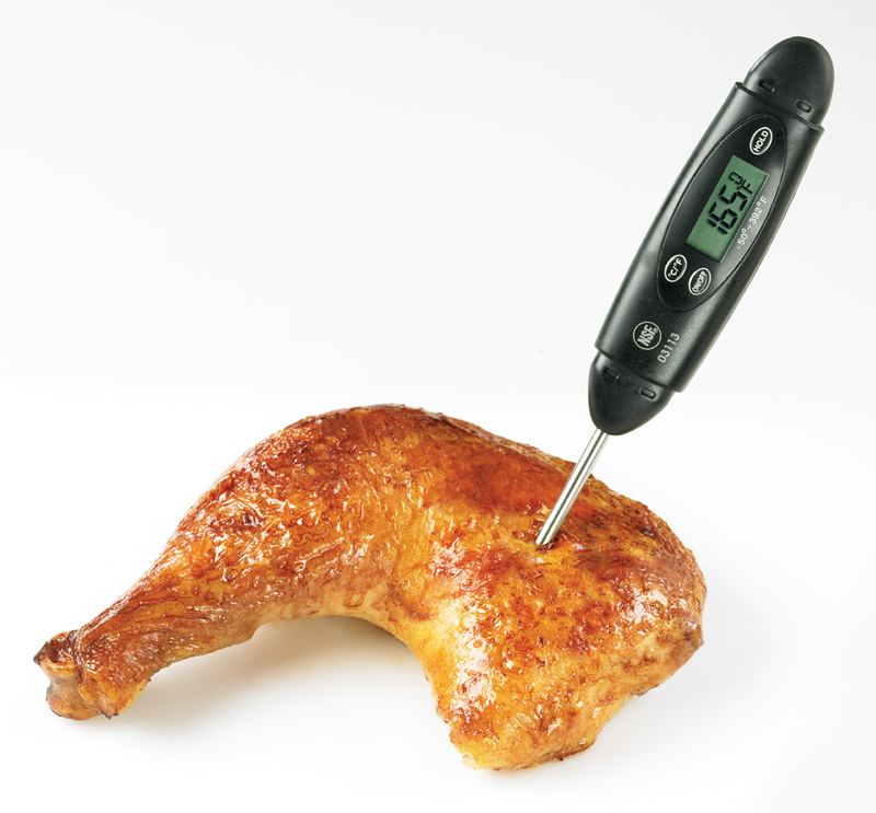
Wall thermometers, outdoor, water thermometers are used to measure the temperature of the medium. The kitchen uses thermometers embedded in brass cabinets and thermometers with a remote sensor. Such thermometers expand the possibilities of the hostess in the preparation of dishes with temperature control: indispensable when preparing steaks and other meat dishes.
Measuring humidity

The humidity in the room is measured by advanced hostesses with hygrometers, less often - psychrometer. But comfort and health in the house is very dependent on humidity. Not overwhelmed, not overwhelmed air is not favorable. To moisturize the overwhelming air, many use humidifiers - appliances that spray small water vapor.
We measure concentrations (ooo ... how difficult!)
The concentration of solutions is measured by special submersible ranges. With the help of sucrometer, the concentration of sugar in water is measured (sugar concentration in grape juice before fermentation of homemade wine). Using a alcoholometer, the alcohol concentration in beverages is measured. A special range is measured by an acid concentration in the battery electrolyte.
We measure tension

To measure the voltage, you must have a voltmeter, and even better - a universal tester. It allows you to measure the variable voltage in the network 220 V, the constant voltage of the batteries and batteries 1-24 V. In addition, the tutor allows you to detect a break in electrical chain, Different light bulb, fuse, etc.
Above briefly described common in everyday life simple measurements. IN lately There have been a lot of electronic household measuring instruments, which increase the accuracy, speed of measurements, provide remote mode, alarm, indication, and register. Follow the update of the range in Comfy: maybe this month has something new in the subject of measuring instruments appeared this month?
If you have found a mistake, please select the text fragment and click Ctrl + Enter..
The measuring device is a device that can display a physical value in a specific range. Its standard design, as a rule, includes a converter that is engaged in changing the information received. All this is necessary in order for a person to have an idea of \u200b\u200bthe study.
At the same time, the data can be obtained by the most different ways. If you talk about digital models, the value under study is capable of displaying on the display through a personal computer. At this time, mechanical instruments for measuring have a scale with an arrow.
What kinds are?
First of all, the measurement devices are classified according to the value determination method. To date, there are only two types: comparative, as well as direct action devices. The first option implies a comparison of two values. At the same time, one of them is known and takes as a basis. Direction devices are measured directly during the reference. According to the degree of indication, the meter instruments are also divided into two types.
The first type is called registering. His feature is that it is capable of fixing the result. As a result, the researcher has the opportunity to ultimately display data in the form of a diagram or graphics. The second type is called showing. The devices of this species are not capable of fixing the final values, and only the real value displays. Thus, the researcher does not have the ability to compare the data after work.
Control and measuring devices
Control and measuring instruments and automation in our time are strongly connected. It should be noted that these devices are designed to refer to the readings. In this case, the data can be displayed in absolutely different ways. Models with a conventional scale are most common. Additionally, the arrow is installed on them. As you know, the scale is called the system of marks. At the same time, numeric values \u200b\u200bare displayed on it. With their help, the researcher can observe changes in the amount.
The main characteristics of the scales are considered to be the length of division, the indication range, as well as the limits of measurements. At the same time they are one-sided or bilateral. Additionally, there are control and measuring instruments with a symmetric scale. These devices can be very easy to identify, because the zero is located strictly in the center. Measuring devices with a naughty scale do not have such properties.
Working devices measurements
Working instrumentation are a separate subspecies of the devices for determining the amount of metrological attribute. They are used in a cup of all in various technical work. In this case, the devices are allocated by the fact that they can be operated in different conditions.
First of all, it is, of course, laboratory devices. With their help, scientists conduct research. In production this species The devices are also found often. There they are responsible for controlling all the processes taking place and monitor various technological indicators to achieve high quality products. Thus, it can be said that the operating instrumentation and automation are highly dependent on each other.
In the field this equipmentCertainly used. Most often it is used for the successful operation of cars and other vehicles. Among other things, experts are used before the attack of aircraft to determine their condition. Additionally, it should be understood that according to the characteristics of the working devices for measurements, it is quite highly different. This is primarily due to the conditions in which they are operated. Thus, the accuracy of measurements is very important for a laboratory assistant. It is absolutely indifferent to which model is able to withstand vibration or temperature.
At this time in production, as a rule, very complex working conditions. In this case, the body of the measurement instrument may be damaged due to the impact. Given this, this class model is more durable. Field devices for measurements are considered universal. They must withstand vibration, as well as work at different temperatures. Also experts are evaluated by their resistance to high level humidity. Not a latter role, naturally, the accuracy of measuring devices plays, but not as much as in the case of laboratory studies.

Optical devices
An optical measuring device is a special device that is capable of making angular measurements. Most often it is used in various areas where it takes a fairly accurate processing of parts. These devices are divided by the type of optical system. In this case, the accuracy of the instruments is determined by a special scheme.
A bright representative of optical models for measurements are microscopes. These system of measuring devices allow scientists to study various parts. In this case, the process is carried out according to rectangular, as well as polar coordinates, taking into account the general angle. They are also used for measurements of templates of complex forms.

Characteristics of optical models
An important characteristic of all optical instruments for measurements are the limits of the value. At the same time, they are estimated both in the longitudinal and transverse direction. In this case, the division value can be determined by two parameters.
First of all, the boundary of the reading device is taken into account, and it is measured in millimeters. In the second case, the number of accelerated head scales is taken into account. Among other things, it is possible to attribute an increase in lens to important characteristics. Also on the accuracy of measurements affects the diameter of the field of view, which is measured in millimeters.
Mechanical instruments for measurements
To date, there are many varieties of mechanical instruments for measuring. Controls are considered the most common. As a rule, they represent the operating line, as well as a lectal type. Their obligations include watching various deviations from straightness. The whole process occurs through the probe.
Sine rules have the ability to make indirect measurements. As a rule, they only work with outer angles up to 45 degrees. In this case, the error they have quite tangible, and this is a clear minus. Verification of measuring instruments is carried out only in specialized centers.
To control various gaps on the entry of the blades there are probes. Testing Calves are able to measure straight angles on the lumen. For visual control of the surface, a separate subspecies of mechanical instruments for measuring is provided, and it is called a roughness device.
FEATURES OF STANDERINSTRANS
Most models of stantlerystruments are two surfaces, between which the subject can be installed. More details are called sponges. In this case, the upper surface is basic and connected to the ruler. At this time, the second sponge can move. The essence lies in the fact that the scale has a scale.
At the same time, the limits of samples are different. The caliper is capable of showing the outer, as well as the internal size of the subject. At the same time, another device is provided for measuring the depths of the grooves. It is called a calorieglubinomer, which also has the ability to make measurements of the heights of the protrusions. In general, measuring instruments and tools are additionally used to work with gear gears.

Measuring heads of devices
The measuring head is called the counting mechanism, which is installed in the instruments. Spring type models have a pretty elastic element in the structure. At the same time, it is completely standardized. Immediately spring is used flat along with a torsion shaft.
Additionally, it can be called a microcrateter. If we talk about optical models, then the optics are used there. At the same time, they are quite compact and relate to small-sized instruments for measuring. The lever-gear heads are the most common type.
They are used, as a rule, in the indicators of the hour view. In this case, the lever can easily change their position. For relative measurements of external dimensions, multi-turn devices are used. The lever bracket is fixed with the reading mechanism. Additionally, it should be noted that the lever-gear heads are installed in the digital meters. There they work for a couple with string converters. They serve mainly for linear measurements.
Micrometric measuring instruments
This type of tool is not very common. The main element of these devices can be called spindle. Distinctive feature This part is a thread with a fairly accurate step. As a result, the spindle is able to perform axial movements.
As a result, the researcher gets the opportunity to count the total turnover of the mechanism. Helps him in this strokes that are applied on a special stem. At the same time, the rollers can count on radial marks. They are applied, as a rule, on the drum of the device. One step of the device is equal to different value. It is considered the most smaller indicator 0.5 mm, however, there are models with a division of 1 mm. To calculate the zero value, the drum can be easily moved.
Thus, the device is easy to configure. The spindle is able to change its position due to spring-loaded ratchet. In some models, a friction clutch is installed instead. She can also be called a rattle. Given all the above, this micrometric measuring device is able to perform a wide variety of tasks. As an example, it can be installed on the brackets. As a result, it will be able to carry out their exact countdown.
Scheme of mechanical meter
A simple kinematic diagram of the transmission mechanism of the indicator is a set of tip, as well as a sleeve. Additionally, there is a measuring rod. It is attached directly to the head in the device. The switched screw is connected to the rim. To display data there is a dial with a pointer.

A more complex diagram of the meter looks different. First of all, the rod in it is immobile, sideworks are supported on nuts. There is also a screw that is attached to the holder. The movable neck is connected to the terminal lengths.
Thus, the bridge in the device is centered. The lever in the scheme has two-beam. At the same time, the rod in the case of the device is located vertically, and the spring is located next to the indicator tip.
Electronic devices for measuring
First of all, the electronic measuring instrument is known for its increased speed. Additionally, it is able to boast of high sensitivity. At the same time, many models have a fairly wide frequency range, which, of course, gives great opportunities in research.
The above devices are used exclusively for electrical dimensions. As a rule, they are used in determining voltage or current in the chain. Also measuring electrical devices allow you to carry out work to determine the resistance.

Digital models
The most common electronic devices It is customary to be digital measuring instruments. They cost quite expensive, however, are simple in circulation. A vivid example of this device is considered voltmeters and ammeters. They are capable of a short time to calculate the exact voltage in the electrical circuit. An integral part of them can be called the converter.
Also in models can be used additionally magnetoelectric devices. Directly the measurement process in this situation is associated with the divider. In this case, the amplifier skips the voltage through the device converter. Thus, the magnetoelectric apparatus is able to make accurate measurements of the magnitude. Naturally, the error in them is present, however, today there are various filters that are fighting with oscillations.

Another example digital model A oscilloscope can be considered, which is actively used in the medical industry. This universal measuring device is able to monitor different signals. At the same time, they can be periodic or not. If necessary, digital measuring instruments (oscilloscopes) are connected to personal computers.
As a result, the frequency change can be observed from the display. It also opens up the possibility of fixing the signal readings. As a result, all data can be analyzed after research. These measuring instruments (market prices) are on average about 20 thousand rubles.
In the modern stormy rhythm of life appliances Allows you to quickly and effectively cope with your home affairs. Often it fully performs work per person. Household appliances have a classification by intended purpose.
Measuring instruments
The main minor technique for measuring various parameters includes:
- Kitchen scales (with bowl, flat, in the form of a decanter to determine the exact weight, with fasteners for hanging).
- Outdoor scales for determining human weight. For weighing children up to ten kilograms, special scales are made with a cuvette.
- Shootlessness. Called to replace scales outside the house (fishing, cottage, market).
- Clock (floor, desktop, fireplace). Manufactured mechanical and electronic.
- Alarms. I can run from various materials (wood, plastic, glass, stone, metal).
- Thermometers for measuring body temperature, indoor air and outdoor, water temperature.
Computer Engineering
 Without the technique of this kind, modern person no longer represents its existence. It includes:
 - calculators ( portable device for computing operations);
- smartphones (functional mobile phone in the form of a mini-computer);
- tablet I. personal computers,
- laptops.
Kitchen appliances
The most extensive segment. For the purpose is divided into several subgroups.
To preserve products
The short-term preservation of products from damage is performed by refrigerators. For longer preservation by freezing, freezers are suitable.For mechanical processing
Eliminates the most difficult and unpleasant work. The mixer makes it possible to quickly mix liquid components. It is used to prepare beverages, creams, mashed potatoes, dough. Grind more dense and hard products using a blender. The transformation of meat into the minced meat grinder. Align all functions in one device allows the kitchen processor.
For thermal processing
Includes electric or gas stove. Induction plates, warming special dishes using induction current use very popularity. For baking, brass cabinets are produced, allowing to use different baked modes.
No less functional are microwaves, bread makers, multicookers, steamers. Thanks to this home appliance, food is delicious and useful. It is enough to put the necessary ingredients there, set the mode and click on the button.
To smaller household appliances relate:
- grill (fries meat on a grid or spit);
- aerium (prepares food by blowing hot air);
- fryer (products are prepared in hot oil);
- toaster;
- waffelnitsa;
- pancake;
- yogurtnitsa;
- steroids for grains and others.
For cooking drinks
A truly delicious coffee is a welded coffee maker made of grasses crushed in a coffee grinder. An even more functional tool is a coffee machine. The ability to boil the water to brew tea, give electric kettle. For the preparation of vitaminized cocktails and juices need a juicer.
Auxiliary machinery
After cooking, there remains unbearable dishes. Dishwasher helps to cope with this. To prevent smell, smoke, evaporation in the kitchen over the stove are made of extracts. Water heaters allow electrical heaters.
Home cleaning equipment
The main device for cleaning the premises is a vacuum cleaner. It can be washing, combining the function of removing dust and washing floors. To eliminate contaminants of various kinds (fat, mold, raid) from the surface of brazers, cranes, tiles without chemicals produced steam cleaners and even steam mops.
Close care technique
The following "helpers" are intended to contain clothing clean and accuracy:- Washing machine for removing contaminants from clothing and other textiles products.
- Drying machine. This folding table with a cap from heat-resistant material is able to dry and stroke clothing.
- Ironing board. Mint clothes are stacked on its surface. The kit usually includes the cord holder, the stand for the iron, the shoe for ironing sleeves.
- Iron. Through the effects of temperature and moisture on clothing are removed.
- Sewing machine. Allows you to make or repaired clothes, lengthen or shorten the product. Modern machines are able to embroider, sew buttons, grind loops and perform a large range of finishing lines.
- Machine for hairstyle, dryers for shoes.
Technique for creating a comfortable microclimate
These include:- air conditioners (heats up, cooled and cleans air);
- cleaners (clean air);
- washing and humidifiers of air (clean and moisturized);
- heating radiators (increase air temperature);
- fans (blown air flow);
- air ionizers (make air fresh and clean).
- weather stations (measure and show the main parameters of the microclimate).
Small household appliances for care
Bring hair in order helps dryers for drying and styling, pliers for curling curls, iron for straightening strands. In the fight against unnecessary "vegetation", epilators and electric shavers are designed to help. The first remove the hairs with the root, the second is cut off, leaving the whole bulb. In the bathroom you can find irrigators (electric toothbrushes) and massagers.Recreation and Entertainment
Thanks to the above home assistants, free time remains. It can be held for listening to music or watching a favorite transfer or film. For these purposes, there is the following technique:- music center (designed to reproduce different types of media);
- player (reproduces audio and video files);
- DVD player (reads and reproduces DVDs);
- television;
- game console;
- radio receiver.
Maria Vyazhad
Women's legs.ru.
Interesting communication - (For the work of comments, a java script is needed in the browser): Please Enable JavaScript to View The
A huge selection of schemes, manuals, instructions and other documentation on different kinds Factory Machinery Measuring: Multimeters, Oscilloscopes, Spectrum Analyzers, Attenuators, Generators, r-L-C meters, Response, nonlinear distortion, resistance, frequency meters, calibrators and much more measuring equipment.
During operation inside oxide capacitors, electrochemical processes are constantly occurring, destroying the place of connection of the output with the plates. And because of this, transitional resistance appears, which sometimes achieves dozens. Current charges and discharge cause heating of this place, which further accelerates the process of destruction. Another frequent reason for the failure of electrolytic capacitors is "drying", electrolyte. To be able to rebel such capacitors we offer radio amateurs to collect this simple scheme
Identification and testing of stabilians turns out to be somewhat more complicated than checking diodes, because for this you need a voltage source exceeding stabilization voltage.
Using this homemade console, you can simultaneously observe on the selected oscilloscope on the screen immediately behind the eight low-frequency or pulsed processes. The maximum frequency of input signals should not exceed 1 MHz. According to amplitude, signals should not be very different, at least there should be no more than 3-5 times differences.
The device is calculated on the test of almost all domestic digital integrated microcircuits. They can check the chips of the K155 series, K158, K131, K133, K531, K533, K555, KR1531, KR1533, K176, K511, K561, K1109 and many others
In addition to measuring the capacity, this console can be used to measure USTAB in stabilitons and verification semiconductor devices, transistors, diodes. In addition, you can check high-voltage capacitors for leakage currents, which helped me with the establishment of a power inverter to one medical device
This prefix to the frequency is used to assess and measure the inductance in the range from 0.2 μH to 4 Gn. And if the C1 condenser is excluded from the circuit then when connecting the coil with a condenser to the input to input, the output will be a resonant frequency. In addition, due to the low voltage value at the contour, the inductance of the coil can be estimated directly in the scheme, without dismantling, I think many repairmen will appreciate this opportunity.
On the Internet there are many different diagrams of digital thermometers, but we chose those that are characterized by their simplicity, small number of radio elements and reliability, and it is not necessary to scare that it is assembled on the microcontroller, because it is very easy to program it.
One of the schemes of the self-made temperature indicator with lED indicator On the LM35 sensor, you can use for visual indication of the plus values \u200b\u200bof the temperature inside the refrigerator and the engine of the car, as well as water in the aquarium or pool, etc. The indication is made on ten conventional LEDs connected to the Specialized LM3914 microcircuit that is used to include indicators with a linear scale, and all internal resistances of its divider possess the same nominal
If you get the question of how to measure the engine speed from washing machine. We will tell a simple answer. Of course you can collect a simple stroboscope, but there is a more competent idea, such as using the Hall sensor
Two very simple clock schemes on microcontroller PIC and AVR. The basis of the first scheme aVR microcontroller Attiny2313, and the second PIC16F628A
So, I want to consider today to consider the next project on the microcontrollers, but also very useful in the daily work of the radio amateur. This is a digital voltmeter on the microcontroller. The scheme was borrowed from Radio magazine for 2010 and can be easily redone under the ammeter.
This design describes a simple voltmeter, with indicator on twelve LEDs. This measuring device allows you to display the measured voltage in the range of values \u200b\u200bfrom 0 to 12 volts in 1 volt increments, and the error in the dimension is very low.
The scheme of the inductance meter of coils and capacitors of capacitors, made in total on five transistors and, despite its simplicity and availability, allows in a large range to determine the container capacity and inductance of coils with an acceptable accuracy. There are four subbands for capacitors and as many as five subbands of coils.

I think most clearly, the sound of the system is largely determined by different levels of the signal at its individual sites. By controlling these places, we can estimate the dynamics of the work of various functional nodes of the system: to obtain indirect data on the gain of the amplification of distortion, etc. In addition, the resulting signal is simply not always possible to listen, therefore, the level indicators are used.
In electronic structures and systems there are faults that occur quite rarely and they are very difficult to calculate. The proposed homemade measuring device is used to search for possible contact problems, and also makes it possible to check the condition of cables and individual lived in them.
The basis of this scheme is the AVR ATMEGA32 microcontroller. LCD Display with a resolution of 128 x 64 points. The scheme of the oscilloscope on the microcontroller is extremely simple. But there is one substantial minus - it is enough low frequency Measured signal, just 5 kHz.
This prefix greatly facilitates the life of the radio amateur, if it has a need for a winding inductor coil, or to determine unknown coil parameters in any equipment.
We offer you to repeat the electronic part of the scales scheme on a microcontroller with a strain gauge, firmware and drawing pCB To the radio amateur development is attached.
Homemade measuring tester has the following Functionality: Frequency measurement in the range from 0.1 to 15000000 Hz with the ability to change the measurement time and display the frequency value and duration on the digital screen. The presence of the generator option with the possibility of adjusting the frequency in the entire range from 1-100 Hz and output results on the display. The presence of an oscilloscope option with the ability to visualize the signal shape and measuring its amplitude value. The function of measuring the container, resistance, as well as voltage in the oscilloscope mode.
The simple method of measuring the current in the electrical circuit is a method for measuring the voltage drop on the resistor connected in series with the load. But when current flow through this resistance, it is generated by an unnecessary power in the form of heat, so it must be selected by the minimum possible value, which significantly enhances the beneficial signal. It should be added that the schemes discussed below make it possible to exceed not only the permanent, but also pulsed current, however, with some distortion, determined by the bandwidth of the amplifying components.
The device is used to measure temperature and relative air humidity. The humidity sensor and the temperature of DHT-11 are taken as the primary converter. The homemade measuring instrument can be used in warehouse and residential premises for monitoring temperature and humidity, provided that it does not require high accuracy of measurement results.
Basically, temperature sensors are used to measure temperature. They have different parameters, cost and form of execution. But they have one big minus, restricting the practice of their use in some places with a large temperature of the measurement object with a temperature above +125 degrees Celsius. In these cases, it is much more profitable to use thermocouples.
The circuit of the intersensional tester and its work is satisfied simple and is available for the assembly even beginner electronics. Thanks to this, the device can check almost any transformers, generators, chokes and induction coils with a par with a par value from 200 μg to 2 GG. The indicator is able to determine not only the integrity of the studied winding, but also perfectly identifies the inter-touch closure, and in addition, they can be checked by P-N transitions in silicon semiconductor diodes.
To measure such an electrical magnitude, as the resistance uses a measuring device called an ohmmeter. Instruments that measure only one resistance in amateur practices are rarely used. The bulk uses typical multimeters in resistance measurement mode. As part of this topic, consider simple schema Ommeter from radio magazine and even more simple on Arduino board.
BMK-MihaThe most important disadvantage of this device is a low resolution - 0.1, which is impossible to increase purely software. If it were not for this lack, the device would be perfect!The ranges of the original scheme: ESR \u003d 0-100Ω, C \u003d 0PF-5000μF.
I want to pay special attention to the fact that the device is still in the process of refinement as software and hardware, but continues to be actively operated.
My modifications are relative:
Hardware
0. Removed R4, R5. Resistance to resistors R2, R3 reduced to 1.13K, and picked up a pair with an accuracy of one Ohm (0.1%). Thus, increased the test current from 1 to 2 mA, while the nonlinearity of the current source decreased (due to the removal R4, R5), the voltage drop on the condenser increased, which helps to increase the accuracy of the ESR measurement.
Well, of course corrected Kusil. U5B.
1. Inserted power filters at the input and output of the converter + 5V / -5V (on the photo the header standing vertically and there is a filter converter)
2. Put the ICSP connector
3. Inserted the switching button R / C (in the "original" modes switched to an analog signal entering RA2, the origin of which in the article is described extremely foggy ...)
4. Introduced the forced calibration button
5. Introduced the buzzer confirming the pressing of the buttons and the feeding signal of the inclusion every 2 minutes.
6. I used the invertors with parallel pairwise inclusion (with a test current of 1-2m, it was not necessary, just dreamed of raising the measurement current to 10mA, which was still failed)
7. Sequentially with P2 put the resistor 51 (in order to avoid KZ).
8. Contrast adjustment has drawn the capacitor 100NF (attacked the indicator). Without it, when you touch the screwdriver, the R7 engine started to consume 300mA! A little LM2930 did not burn with the indicator!
9.An the nutrition of each MS put the blocking capacitor.
10. Adjusted a printed circuit board.
Software
1. Removed the DC mode (most likely I will return it back)
2. Introduced the table correction of nonlinearity (at r\u003e 10Ω).
3. Restricted the ESR range to 50 (with the original firmware the device "Cashkalivaya" at 75.6 Ohm)
4. add a calibration subroutine
5. Wrote support for buttons and buzzer
6. Introduced the battery charge indication - numbers from 0 to 5 in the last discharge of the display.
Neither the hardware is not interfered with the tank measurement unit, except for the addition of the resistor sequentially with P2.
The principal scheme reflecting all the refinement has not yet drawn.
the device was very sensitive to humidity!how to smoke at him so the testimony begin to "swim". There is a large resistance of R19, R18, R25, R22. By the way, can someone explain to me, na nah * cascade on u5a such a big input resistance ???
In short, the analog part poured varnish - after which the sensitivity completely disappeared.
Elektor magazine As far as I know, German, the authors of the articles of Germans and print it in Germany, at least the German version.
m.IX.let's joke in the flame
Here, issues of independent manufacture and operation of measuring devices used in amateur radio practices are considered.
Homemade radio amateur instruments.
Homemade and industrial measuring instruments based on a computer.
Industrial measuring instruments.
Updated file archive on the topic "Measuring instruments" is , Over time, I hope to prepare a review with comments.
Functional generator swinging frequency and tonal parcels.
This article is a report on the work done at the beginning of zero years, in those days, the independent manufacture of measuring instruments and the equipment of its laboratories for radio amateurs was considered common. I hope that those who are passionate and interested craftsmen meet now.
Prototypes for the considered FGCC steel "Tonal parcel Generator" of Nicholas Sukhova (Radio No. 10 1981 p. 37 - 40)
and "Prefix to the Oscilloscope for Observation of ACH" O. Suchkov (Radio No. 1985 pp 24)
Scheme of the prefixes O. Suchkov:

Designed based on specified sources and other literature (see notes in the field fields) FGCC forms the voltages of sinusoidal, triangular and rectangular (mandrel) shape, amplitude 0 - 5V with step-20, -40, -60 dB in the frequency range of 70Hz - 80kHz. FGCC regulators can specify any section of swing or frequency jumps, when generating packs, inside the operating frequency range.
Control and synchronization of the frequency restructuring is carried out by increasing sawtooth voltage of the oscilloscope.
FGKC allows you to quickly evaluate frequency response, linearity, dynamic range, reaction to pulse signals and the speed of analog radio-electronic sound-range devices.
FGCC scheme is presented on Figure.

Scheme in high resolution is or loaded by clicking on the drawing.
In the swinging frequency mode, the input of the A4 is served a sawdust voltage from the oscilloscope expulsion unit (as in the GCC scheme O. Suchkov). If the A4 frequency control input is not served, but the meander, the frequency will change the jump with low to high. The formation of the model from the saw is made by the usual Schmitt trigger, on transistors T1 and T2, of different conductivity. C exit TSH MANDRD enters the electronic key A1 K1014T1, designed to match the voltage level of the fgkch controller in frequency. The + 15V voltage is given to the key input, from the key output, the rectangular signal is supplied to the OU A4 input. Switching frequency occurs in the middle part of the horizontal expandment, synchronously. After AU A4, there are two EPs on T7 transistors - PNP and T8 - NPN (for thermocomponation and leveling of the level shift) in the Emitter T7 there is an alternating resistor RR1, which sets the lower border of the swing or forming pulse packs in the range of 70Hz - 16 kHz. The R8 resistor (for suchkov) is replaced by two RR2 - 200kom and RR3 - 68 com. RR2 sets the upper limit of the swing range 6.5 - 16.5 kHz, and RR3 - 16.5 - 80 kHz. The integrator to the OU A7, Trisheg Schmitt on the OU A7 and the switch phase switch of the A5 - T11 amplifier transmission coefficient, work as described in O. Suchkov.
After the buffer amplifier, the signal shape switch with triangle levels and PR7 is adjustable to OU A7. normalizing output signals. The sinusoidal signal generator consists of an A8 OE - which does not invert the amplifier with an increase in the amplification in the range 1 - 3 times (PR3 stroke resistor) and the classical saw-shaped voltage converter into the sinusoidal field transistor T12 - KP303E. From the source T12, the sinusoidal signal is supplied to the S2 pulse selection directly, since the level of the sinusoidal signal is determined by the normalizing amplifier on the A8 A8 and the value of PR3. From the output of the RR4 level controller, the signal is supplied to the buffer amplifier on the A9 buffer. The gain of the buffer amplifier is about 6, sets the resistor in the OU Feedback Circuit. On T9B T10 transistors and S3 switches, S5, the synchronization node used to test the recording path is not currently not relevant. All OU - with PT at the entrance (K140 UD8 and K544AUD2). Double-blood pressure voltage stabilizer +/- 15B, assembled on OU A2 and A3 - K140UD6 and T3 - CT973 transistors, T4 - KT972. Sources of current of stabilion of support voltage on PT T5, T6 - KP302B.
Working with the functional GCC under consideration is made as follows.
The S1 switch "mode" is set to the "FILN" position and a variable resistor RR1 "FISH" The lower frequency of the swing range is set, or a smaller frequency of pulse packs, in the range of 70Hz - 16 kHz. After that, the switch S1 "Mode" is set to "FOP" and RR2 "6-16 kHz" and RR3 "16 - 80CHC" variable resistors "6-16 kHz" and RR3 "16 - 80 kHz" is set to the upper frequency of the swing range, or a high frequency of pulse packs, in the range of 16 - 80 kHz. Next, the S1 switch is translated into the "Kach" or "packs" position to form the output voltage of the swing frequency or two packets of the pulses of the smaller and greater frequency condensed synchronously with the spread, when the beam passes through the middle of the screen (for pulse packs). The output shape is selected by the S2 switcher. The signal level is adjustable in a variable RR4 variable resistor and stepwise switch S4.
Oscillograms of test signals in the "frequency swing" and "packs" modes are presented in the following pictures.


Photo generatorassembly, presented in the figure.

In the same case, the broadband sinusoidal voltage and meander generator (important: R6 in the diagram of this generator - 560kom, and not 560, as in the figure, and if instead of putting a pair of a permanent resistor with 510kom and a trimming 100kom, you can adjust the trimmer, set the minimum possible kg.)
and frequency meter whose prototype is described in.
It is important to note that in addition to checks the analog paths of sound-reproducing equipment, in the frequency swing modes and the formation of frequency packages, the functional GCC can be used and simply as a functional generator. Triangular shape signals help very clearly track the occurrence of restrictions in amplifier cascades, set the signal limitations symmetrical (the fight against harmonics is more visible on the ear), check the presence of a "step" type distortion and evaluate the linearity of the cascade as the front and recess of the triangular signal is curved.
An even more interesting is the inspection of the umzch and other sound units, a rectangular signal, with a 2-meander bed. It is believed that for the correct reproduction of the meander of a certain frequency, it is required that the working (without weakening) is a strip of the tact of the tact, was at least ten times larger than the frequency of the test meander. In turn, the bandwidth of the frequency band reproducible, for example, the umzch determines such an important qualitative indicator as the coefficient of intermodulation distortion, so significant for the lamp UMPs, which is not fully measured and not published and not published in order not to disappoint the public.
The following figure is a fragment of Y. Solntsev article "Functional" generator "from the radio company.
On the image- Typical distortions of meander, arising in the sound tract, and their interpretation.

Even more visual, measurements with functional generatorcan be produced, feeding a signal from its output to the x oscilloscope input, directly, and on the Y input through the device under study. In this case, the screen will display the amplitude characteristic of the scanned circuit. Examples of such measurements are shown in the figure.

You can repeat my version of the functional GCC, as it either or accept it for alpha - the version of your own design, made on a modern elementary base, with the use of circuitry solutions that you consider more progressive or affordable. In any case, the use of such a multifunctional measuring device will allow you to significantly simplify the setting of sound-reproducing paths and controlled to increase their qualitative characteristics during the development process. It is certainly right only if you think that to customize the schemes "for rumor" - a very dubious reception of radio amateur practice.
Machine for the inclusion of waiting mode for oscilloscope C1-73 and other oscilloscopes with a regulator "Stability".
Users of Soviet and imported oscilloscopes equipped with a regulator of the expandment mode "Stability" came across working with the following inconvenience. Upon receipt on the screen stable synchronization of the complex signal, the stable image is stored until the signal is sent to the input or its level remains fairly stable. With the disappearance of the input signal, the expandment can remain in waiting mode how many things are long, and the beam on the screen is missing. To switch the expandment into an auto-oscillating mode, sometimes just slightly rotate the "Stability" knob, and the beam appears on the screen, which is required when binding the horizontal expansion to the scale grid on the screen. When measuring the measurement, the image on the screen can "swim" until the regulator "stability" will not be restored waiting mode.
Thus, in the measurement process, it is necessary to constantly twist the "Stability" knobs and the "synchronization level", which slows down the measurement process and distracts the operator.
The proposed refinement of the C1-73 oscilloscope and other devices-like (C1-49, C1-68, etc.) equipped with a regulator "Stability", provides for automatic change in the output voltage of the variable resistor of the regulator "Stability", which translates the operating unit of the oscilloscope in an auto-oscillating mode in the absence Input sync signal.
The scheme of the automatic switch "Waiting - auto" for oscilloscope C1-73 is shown in Figure 1.

Picture 1. Scheme of automatic switch "Waiting - Auto" for oscilloscope C1-73 (Click to enlarge).
On the transistors T1 and T2, a single-tram, started, through the C1 condenser and diode D1 pulses of a positive polarity from the output of the launch pulse former extends oscilloscope C1-73 (checkpoint 2GH-3 block U2-4 in Figure 2)

Figure 2.
(Fully, the C1-73 oscilloscope scheme is here: (Fig5) and (GIF 6)
IN initial state, in the absence of inclusive pulses, all transistors of the "Waiting - auto" automaton are closed (see Fig. 1). Diode D7 is open to the right according to the scheme (cm. Fig. 2) The output of the variable resistor R8 "Stability", according to the chain R11 D7, a constant voltage is supplied, which translates the expandment generator into an auto-oscillating mode, with any position of the variable resistor R8 "stave".
At the arrival of the next impulse, the launch of the expandment, the transistors T2, T1, T3, T4 are sequentially open, and the diode D7 is closed. From this point on, the synchronization circuit of the oscilloscope C1-73 is operating in a typical mode specified by the voltage at the output of the variable resistor R8 (see Fig. 2). In the particular case, the waiting time of the expandment can be set, which ensures the stable position of the image of the signal under study on the oscilloscope screen.
As mentioned above, when the next sync pulse is received, all transistors of the distributor management machine are opening, which leads to a quick discharge of the electrolytic capacitor C4 through D4 diode, an open transistor T2 and a R5 resistor. Capacitor C4 is in a discharged state, all the time until the input of the simultant is received by triggering pulses. Upon completion of the receipt of launch pulses, the T2 transistor closes, and the C4 condenser begins to charge the base current of the T3 transistor through the R7 resistor and D5 diode. Capacitor C4 charging current supports T3 and T4 transistors open, retaining the waxing mode, set by the voltage at the output of the variable resistor R8 "Stability" for several hundred milliseconds, waiting for the next Syr Omplus. If such does not arrive, the T3 transistor closes completely, the LED D6, indicating the inclusion of the waiting mode, goes out, the T4 transistor is closed, the diode D7 opens and the oscilloscope expandment turns into an auto-oscillating mode. To ensure an accelerated transition to waiting mode, when the first sync pulse is received in the series, an element "logical or" on diodes D3 and D5 is applied. When the simultor is triggered, leading to the opening of the transistor T2, the T3 transistor opens without a delay, along the circuit R7, D3, R5 before the end of the C4 condenser discharge. It may be important if you need to observe single pulses in waiting synchronization mode.
The assembly of the waiting mode of the waiting mode is made of volumetric installation.

Figure 3. Complete installation of the waving automaton of the oscilloscope.

Figure 4. Isolation of elements machine of waiting for oscilloscope mode with paper inserts and molten paraffin.
Before mounting, the module is in a strip of paper, cursed with transparent scotch, at least on the one hand, just to reduce leaks. The side of the paper, copened by scotch, is addressed to the collected module. The volumetric installation of the machine allowed to reduce the assembly time and abandon the development and manufacture of printed circuit board. In addition, the modules turned out to be compact enough, which is important when they are installed in a small-sized oscilloscope case C1-73. In contrast to the fill of the device collected by volume mounting, epoxy compound and TP solid resins, the use of paraffin allows you to maintain the mainfoldability of the device and the possibility of its refinement, if necessary. In amateur practice, with piece manufacturing, it can be an important factor in the choice of constructive execution of the device.
The type of modular modes mounted on a U2-4 board, oscilloscope C1-73, is shown in Figure 5.

Figure 5. Placing the module of the modulus of the waiting mode on the synchronization board of the oscilloscope C1-73.
The LED indicating the inclusion of waiting mode is sampled by 15 mm. The right level level is shown in Figure 6.

Figure 6. Placement of the waiting mode indicator on the Oscilloscope facial panelC1-73.
The experience of operating the oscilloscope C1-73, equipped with an automatic activation of the waiting mode of the expansion, showed a significant increase in the efficiency of measurements associated with the absence of the need to rotate the stability knob when setting the line to the desired division of the screen grid and then to achieve a stable image position on the screen. Now, at the beginning of the measurements, it is enough to install the level and stability controllers, to a position that provides a fixed image of the signal on the screen, and when removing the signal from the oscilloscope input, the horizontal line of the expansion appears automatically, and the stable picture is returned to the signal.
You can purchase a similar machine waiting for the oscilloscope, saving time to assemble. Use the feedback button. :-)
The block of protection and auto powerwiseing multimeter M830 and to him like "digital Chinese multimeters".
Digital multimeters built on the ADC family (domestic analogue), due to its simplicity, highly accurate accuracy and low cost are very widely used in amateur practice.
Some inconvenience of the use of the device is associated with:
- The lack of auto powerwiseing multimeters
- relative high-cost ninety-coolest large capacity batteries
- the absence of overstrain protection (with the exception of the fuse by 0.25a)
Various ways to solve the above-mentioned problems were offered by radio amateurs before. Some of them (the protection of the ADC multimeter, auto-disconnect, and its power supply from low-voltage power supply, through an increase in the converter, refinements and measurement consoles to the M830 family multimeters.
I bring to your attention another option of the finalization of the "digital Chinese multimeter" on the ADC 7106, combining four important, for such devices, consumer functions: Timer's auto disconnection A few minutes after switching on.
- Overvoltage protection with galvanic disconnection UIR input jack from the multimeter circuit.
- Auto power connection when triggered protection.
- Semiautomatic delay of auto power desk with long measurements.
To explain the principles of work and interaction of the nodes of the Chinese multimeter on IC7106, use two schemes.

Fig.1 - One of the options for the M830B multimeter scheme (click to enlarge).
The diagram of your multimeter may be different or may not be in general - it is only important to determine the power points on the ADC IC and the contact points of the relay, turn off the power and input of the UR instrument. For this, usually, it is enough to carefully consider the multimeter printed circuit board, coping with a datashet on IC7106. or Kr572pv5.Points of connection and tie in the circuit / printed installation of the multimeter are shown in blue.

Fig.2Actually scheme blockers and auto-powerwiseing multimeters (click to enlarge).
The scheme includes a multimeter overload sensors on transistor optocouplers U1 and U2 - AOT128, a comparator on a low current consumption OU - U3 KR140UD1208, key MOS transistor U4 auto-disconnecting timer - KR1014T1. Switching UIR input and multimeter supply voltage, performed by contact groups of a two-winding polarized PR1 relay - RPS-46.
The operation of the protection block and auto discontinuity of the multimeter.
Turning on the multimeter and auto discontinuity to brake timer.
In the initial state, all elements of the multimeter and the protection block are de-energized. The cake of the polarized PR1 relay is closed in positions 1-4 and 6-9 ( see rice. 2.). Multimeter UR input, disabled, the input divider is closed on the general wire - the "COM" connector. The "plus" output of the battery power is disabled from all consumers as the KN1 button "On" and contacts 5-9 PR1 relays are open. The electrolytic capacitor C2, the capacity of which determines the time of operation of the multimeter to auto power, is discharged through closed contacts 6-9 PR1 relay and the multimeter schema.
When you click on the button KN1 "ON", the current from the battery, passing through the winding 2-8 PR1 relay, the C2 capacitor charges. In this case, the contacts 6-9 and 1-4 are blurred, and contacts 5-9 and 10-4 are closed. The Multimeter UR input is connected to the diagram of closed contacts 10 - 4, the PR1 relay, and the battery power supply is supplied through closed contacts 5 - 9, respectively. In the standard modes of the multimeter, the voltage from the output 37 of the DSC IC7106, supplied to the inverting input (output 2), OU U3, turns out to be larger than the direct input (output 3), at the OU output, output 6, voltage is installed. low levelinsufficient to open the transistor T1. The electrolytic condenser, charged by pressing the KN1 button "ON", through the winding 2 to 8 PR1 relay to the supply voltage (9B), after releaseing the KN1 button, starts slowly discharged through the R11, R12 divider. Until then, the voltage on the shutter of the MOS transistor U4 will not decrease to the level, approximately 2B, the transistor U4 remains in the open state, maintaining the D6 diode in the closed state.
Multimeter works in normal mode.
When the voltage drops on the R11, R11 divider below 2B, the transistor U4 is closed, the positive voltage through the R13 resistor and D6 diode enters the output 3 OU4, which leads to the appearance of positive potential at the OU output (output 6) and opening the T1 transistor, the collector of which Connected to the output 7 relay PR1. Through winding 3 - 7, the PR1 relay, causes the reverse switching of the PR1 relay contact groups. At the same time, the contacts 10 - 4 are open (the UR input of the multimeter is turned off) and 5 - 9 (the battery is turned off from the circuit). There is a multimeter autotlope with opening the input circuit.
Semi-automatic detection of the auto-disconnect timer.
If during the operation of the multimeter, repeatedly press the button "On", the current passing through the winding 2 to 8 the PR1 relay, it will recharge the C2 condenser, extending the time interval of the multimeter state. The state of contact groups of the polarized relay PR1, while not changing.
Forced disabling multimeter.
Forced multimeter shutdown can be performed in two ways.
- As usual, the switching switch selection / measurement mode switch to the OFF position is "turned off". In this case, the state of the contact groups of the polarized relay PR1, and the UIR input does not change and the resistant multimeter connected to the resistive divider.
- When you press the KN2 button "OFF", the positive voltage, through the R5 resistor, is supplied to the input 3 UU U3, increasing its potential, compared with the reference voltage (-1B) on the inverting input of the U3 - output 2. This leads to the opening of the transistor T1 and the appearance of current in the "turning" winding of 3 - 7, polarized PR1 relay. At the same time, the contacts 10 - 4 are open (the UR input of the multimeter is turned off) and 5 - 9 (the battery is turned off from the circuit). There is a multimeter autotlope with opening the input circuit.
AutoCillion of the multimeter in the event of overload.
The most likely cause of failure, a multimeter based on the ADC family 7106, is the feed to its measuring input (output 31), voltage exceeding the supply voltage applied to the output 1, relative to the total wire (output 32). In general, when powering a multimeter from the battery with a voltage of 9V, it is not recommended to fed to the input of the DAC, the output 31, voltage, more than 3B, in any polarity. In the previously described schemes for protecting the digital multimeter type M830, it was proposed to turn on a pair of counter-parallel to the included stabilodins between the input of the DAC and the overall wire. At the same time, a high-resistant resistor of the input RC FNH DAC (R17C104 in the scheme on Fig. one), I limited the current through Stabilians at a safe level, however, the resistive multimeter divider and the circuit breakers of the printed circuit board remained unprotected, playing the role of additional fuses and burning during overload.
In the proposed block of protection and auto-powerwiseing multimeter, elevated, over the permissible, voltage at the input of the R17C104 input (see Fig. 1), is used to form a signal of turning off the input socket, with shunting the signal input of the multimeter to the case. The signal of overvoltage is formed by two counter-parallel inclised circuits D1, D2, U1.1 and D3, D4, U2.1, consisting of sequentially connected: silicon diode., LED of green luminescence and LED diode-transistor optro. Such chains performing, as well as the function of passive protection, are widely used in the input cascades of oscilloscopes (for example,). Upon reaching, at a point A, voltage exceeding 3B, in any polarity, diodes (D1, D2, U1.1 or D3, D4, U2.1), in the corresponding chain begin to open, shunting the input of the multimeter into the general wire. In this case, the LED U1.1 or U2.1 one of the optopar, begins to glow, causing the corresponding optotransistor U1.2 or U2.2. The current, with a positive power bus, through the open optotransteristor, is supplied to the unconforming input of the UU U3, causing an increase in the potential at the OU output (output 6) and the opening of the T1 transistor. Current via the T1 transistor and the winding connected to it 3 - 7, the polarized PR1 relay, leads to the opening of the contacts 10 - 4 (the Multimeter UR input is turned off) and 5 - 9 (the battery is turned off from the circuit). There is a multimeter autotlope with opening the input circuit.
The multimeter switches to the off state with the opening of the UIR input.
Structurally, the protection and auto power supply module is made by mounting and placed in the multimer housing, from the reverse side of the measurement range switch. ( see fig. 3.)
In the modified Multimeters of the DT830-C brand ( 0 ), There is no mode for measuring the gain of transistors, which made it possible to place the button on and off the device on the spot, where the terminal block of transistors connects is usually installed. The off button is taken with a higher pusher so that when carrying and stored, with random pressures, it triggered with a greater probability.
The practice of using the protection device and auto discontinuity implemented in two Chinese digital

When working, you can act in two ways, after selecting the conductivity and type of the transistor (bipolar / field (about field - hereinafter)).
1) We connect the transistor, and twist the knob of the base resistor before the generation appears. We understand that the transistor is working and has a certain transmission coefficient.
2) I exhibit a predeterminable transmission ratio and, connecting, in order, the available transistors, select the appropriate requirements.
I made two modifications to this meter.
1) A separate fixed button includes a resistor resistor to the "base" of the transistor, 100 com, grounded from the other side. So the meter can check the field transistors with the P-N transition and P or N channel (KP103 KP303 and the like). Also, without alteration, in this mode, you can check MOP transistors with an insulated shutter N- and P-type (IRF540 IRF9540 ITP)
2) In the collector of the second transistor of the measuring multivibrator (the output of the signal), I turned on the detector with doubling, along the usual scheme loaded to the CT 315GO base. Thus, the transition of this key transistor is closed when generation arises in the measuring multivibrator (the transmission coefficient is determined). The key transistor, opens, grounds the emitter of another transistor, on which the simplest generator with a resonator on a three-way Piezoelement is a typical generator diagram call signal "Chinese" phone. Fragment of the multimeter scheme - the transistor check node - shown in Fig. 3.

Such a circuit reincorder was caused by the desire to use the same calling generator in the overload signal overload alarm node (the first, assembled by me, according to the mentioned scheme, the test parameters of the transistors, was built into LBP Fig.4).

The second meter was embedded homemade to a multifunctional switching multimeter, where one three-wheel drive piezo-emitter was used as a warning device in the "Prober" mode (audio check of short circuit) and test transistors. five.

Theoretically (I did not try), this test can be converted to check powerful transistors by reducing, for example, an order of resistance to resistors in the strapping of the test transistor.
It is also possible to fix the resistor in the base chain (1st or 10 com) and change resistance in the collector chain (for powerful transistors).
Avometer, the diagram of which is shown Pa Fig. 21, it is possible to measure: constant currents from 10 to 600 mA; constant voltages from 15 to 600 V; voltage variables from 15 to 600 V; Resistance from 10 Ohm to 2 MΩ; High frequency voltages 100 kHz-100 MHz in the range from 0.1 to 40 V. The gain of the current transistors in up to 200.
To measure high frequency stresses, a remote probe is used (RF head).
Appearance The autometer and RF head are shown in Fig. 22.
The device is mounted in aluminum housing or in a plastic box with dimensions of approximately 200x115x50 mm. Facial panel from sheet textolite or Ghetinaks 2 mm thick. Case and front panel can also be made of 3 mm thick plywood, impregnated with bakelite varnish.
Fig. 21. Avometer scheme.
Details. Micro ammeter type M-84 per current 100 μA with internal resistance 1 500 ohms. Variable TC type resistor with WC1 switch. The switch must be removed from the resistor body, rotate 180 ° and put on the previous place. Such a change is made so that the contacts of the switch are closed when the resistor is fully removed. If this is not done, the universal shunt will always be connected to the device, reducing its sensitivity.
All permanent resistors, except R4-R7, should be with the tolerance of resistance rates of no more than ± 5%. Resistors R4-R7 Shunting device when measuring currents - wire.
The remote controller for measuring high frequency stresses is placed in an aluminum case from an electrolytic capacitor, its parts are mounted on a plate of plexiglass. It also fastens two contacts from the plug, which are a probion input. The conductors of the input chain should be positioned further from the conductors of the output chain of the probe.
The polarity of the probique diode should be only like this as in the diagram. Otherwise, the appliance arrow will deviate in the opposite direction. The same applies to the autometer diodes.
The universal shunt is made of wire with high resistivity and are mounted directly on the sockets. For R5-R7, the constantanovaya wire with a diameter of 0.3 mm is suitable, and for R4 you can use a resistor of the VS-1 resistance of 1400 ohms, wound on its body a constantane wire with a diameter of 0.01 mm so that their overall resistance is 1,468 ohms.

Figure 22. Appearance of the automera.
Graduation. The automera scale is shown in Fig. 23. The graduation of the Voltmeter scale is produced according to the reference control voltmeter of a constant voltage according to the diagram shown in Fig. 24, a. The source of constant voltage (at least 20 V) may be a low-voltage rectifier or battery made up of four KBS-L-0.50. By turning the engine of the variable resistor, they are applied on the scale of the homemade instrument with a mark of 5, 10 and 15 b, and between them - four divisions. On the same scale, voltages up to 150 V are measured and multiplying the instrument readings by 10, and voltages up to 600 V, multiplying by 40 instrument readings.
Current measurement scale up to 15 mA should accurately correspond to the voltmeter scale of constant stresses, which is verified by the reference milliammeter (Fig. 24,6). If the autometer readings differ from the testing of the control device, then changing the length of the wire on the R5-R7 resistors, customize the resistance of the universal shunt.
In the same way, the voltmeter variable voltage scale is graduated.
To graduate the scale of the Ommeter, you need to use a resistance store or use constant resistors as ± 5% tolerance as reference. Before you begin a graduation, the R11 resistor of the autometer is set the device arrow to the extreme right position - against the number 15 of the DC and voltage scales. It will be the "0" ohmmeter.
The range of resistance measured by an autometer is large - from 10 ohms to 2 MΩ, the scale is tight, therefore only the digits of resistance of 1 com, 5 com, 100 com, 500 com and 2 mΩ are applied on the scales.
Avometer can be measured by a static gain of the gain of transistors for the current of up to 200. The scale of these measurements is uniform, therefore it is divided into equal gaps in advance and check on transistors with known values \u200b\u200bof Emboss if the instrument readings are somewhat different from actual values, then resist resistor R14 to valid values These parameters of transistors.

Fig. 23. Autometer scale.

Fig. 24. Conducting schemes Voltmeter scales and a molometermmeter of an automera.
To test the remote probe, when measuring high-frequency voltage, VKS-7B voltmeters are needed and any high-frequency generator in parallel to which the probe is connected. The wires from the probe include a "common" and "+15 V" autoscole. The high frequency is fed to the input of the lamp voltmeter through an alternating resistor, as when the variable voltage scale is graduated. The testimony of the lamp wagthmeter should correspond to the 16-voltage voltage scale.
If the readings when checking the instrument on the lamp voltmeter do not coincide, then somewhat change the resistance of the resistor R13 probe.
Using the probe, high frequency voltages are only up to 50 V. With a larger tension, a diode breakdown may occur. When measuring frequency voltages above 100-140 MHz, the device contributes significant measurement errors due to the shunting action of the diode.
All the calibration marks on the Ommeter scale make a soft pencil and only after checking the accuracy of measurements, they will drag their ink.
V.V. Remain. To help a school radio framework
Key tags: measurements, rash
This device, meter ESR-RLCF., collected in the number of four pieces, work wonderful and daily. It has great measurement accuracy, there is a software correction of zero, easy to establish. Before that, there was a lot of different devices on the microcontrollers, but all of them are very far away. It is necessary to pay only due attention to the inductor inductance. It should be big and wound as thick wire.
Scheme of the Universal Measuring Device
The capabilities of the meter
- ESR electrolytic capacitors - 0-50 ohms
- Capacity of electrolytic capacitors - 0.33-60 000MKF
- Capacity of non-electrolithic capacitors - 1 PF - 1 μF
- Inductance - 0.1 μH - 1 GG
- Frequency - up to 50 MHz
- The supply voltage of the device - Battery 7-9 V
- Current consumption - 15-25 mA
In ESR mode, they can measure constant resistance 0.001 - 100 ohms, measuring the resistance of circuits having inductance or capacitance is not possible, since the measurement is performed in a pulse mode and the measured resistance is spoiled. To correctly measure such resists, you must press the "+" button. At the same time, the measurement is performed when constant toke. 10ma. In this mode, the range of measured resistance is 0.001 - 20 ohms.

In the frequency mode, when the "LX / CX_PX" button is pressed, the "pulse counter" function is activated (continuous account of pulses of entering "FX"). Zeroing the meter is made by the "+" button. There is an indication of the discharge of the battery. Automatic shutdown - About 4 minutes. After the idle time expires ~ 4 min, the "StBY" inscription lights up and within 10 seconds, you can press the "+" button and work will continue in the same mode.

How to use the device
- Turning on / off - Short-term pressing "ON / OFF" buttons.
- Switching modes - "ESR / C_R" - "LX / CX" - "FX / PX" - "SET" button.
- After turning on the device switches to ESR / C measurement mode. In this mode, a simultaneous measurement of ESR and the capacity of electrolytic capacitors or permanent resisters is 0 - 100 ohms. When the "+" button is pressed, the resistance measurement is 0.001 - 20 ohms, the measurement is performed at a constant current of 10 mA.
- The zero setup is necessary, each time the probe is replaced or when measured using an adapter. Installation of zero is performed automatically by pressing the appropriate buttons. To do this, closure the probes, press and hold the "-" button. The display will appear ADC without processing. If the values \u200b\u200bon the display differ more than +/- 1, press the "SET" button, and the correct value "EE\u003e XXX
- For the measurement mode of constant resistances, zero installation is also necessary. To do this, closure the probe, press and hold the "+" and "-" buttons. If the values \u200b\u200bon the display differ more than +/- 1, press the "SET" button, and the correct value "EE\u003e XXX
Design detection

As a probe, a tulip metallic plug was used. To the central withdrawal of the needle. Side seal - case from a disposable syringe. From the available material for the manufacture of the needle, you can use a brass rod with a diameter of 3 mm. After some time, the needle is oxidized and to restore reliable contact, it is enough to wipe the tip, shallow emery paper.
Details of the device
- LCD indicator based on the HD44780 controller, 2 lines of 16 characters or 2 lines of 8 characters.
- Transistor PMBS3904 - any n-p-nClose by parameters.
- Transistors BC807 - any P-N-P, close by parameters.
- Field transistor P45N02 - Fits almost any of motherboard Computer.
- Resistors in the circuits of current stabilizers and DA1 - R1, R3, R6, R7, R13, R14, R15, should be as indicated in the scheme, the rest can be close at face value.
- Resistors R22, R23, in most cases are not needed, while the output of the "3" indicator should be connected to the housing - it will correspond to the maximum contrast of the indicator.
- The outline L101 - must be necessarily adjusted, the inductance of 100 μg with the middle position of the core.
- C101 - 430-650 low TKE PF, K31-11-2-G - can be found in Kos domestic televisions 4-5 generations (KVP contour).
- C102, C104 4-10 μF SMD - can be found in any old computer motherboard.
- Pentium-3 near the processor, as well as in Pentium-2 boxing processor.
- Chip DD101 - 74HC132, 74HCT132, 74AC132 - They are also used in some motherboards.
Discuss an article universal measuring instrument