What a resistor looks like 50 com. Analog Calculator-Cheat Sheet to determine the ratings of resistors with color marking. Resistors: their appointment, application and measurement
Length Converter Length Converter Mass Converter Volume Resume Products and Food Converter Square Converter Volume and Units Measurement In Culinary Recipes Temperature Converter Converter Pressure, Mechanical Voltage, Module Jung Converter Energy and Operation Converter Power Converter Power Converter Time Converter Linear Speed \u200b\u200bFlat Angle Converter thermal efficiency and fuel efficiency converter numbers in various systems Request Converter Units Measurement Currency Currency Courses Sizes of Women's Clothing and Shoes Sizes Men's Clothes and Shoes Converter Corner Speed \u200b\u200band Rotation Converter Speed \u200b\u200bConverter Corner Acceleration Converter Density Converter Specific Corveter Moment Moment Moment Converter Moment Mount Rotation Converter Converter Specific Correction ) Fuel combustion density converter and specific heat combustion converter (by volume) temperature difference converter thermal expansion converter thermal resistance converter specific thermal conductivity Converter Specific capacity Energy exposure converter and thermal radiation converter Heat flow converter Heat transfer coefficient converter Masse consumption converter Converter Molar consumption Mass flow density converter Converter molar concentration Mass concentration converter in solution Dean Converter MIC (absolute) viscosity kinematic viscosity converter Surface tension converter Parry permeability converter Parry permeability converter and steam transfer speed converter Microphone sensitivity converter Sound pressure level converter (SPL) Converter Light Converter Light Converter Resolution Converter in computer graphics frequency converter and wavelength optical power in diopters and focal length Optical power in diopters and an increase in lenses (×) Electrical charge converter Linear charge density converter Surface density charge Converter Cell density converter Converter electric current Linear Density Converter Surface Density Converter Current Electric field power converter Electrostatic potential converter and voltage converter electrical resistance Specific Electrical Resistance Converter Electrical Conductivity Converter Specific Electrical Conduance Electrical Capacity Inductance Converter Converter American Wiring Caliber Levels in DBM (DBM or DBMWT), DBV (DBV), Watts, etc. Units Magnetotor Converter Magnetic Flow Converter Magnetic Converter Magnetic Field Converter Induction radiation. Power converter absorbed dose of ionizing radiation radioactivity. Radioactive decay converter radiation. Converter exposure dose radiation. Converter absorbed dose converter decimal consoles data transmission converter units typography and image processing converter units of measurements of the volume of timber calculation of the molar mass Periodic system of chemical elements D. I. Mendeleev
1 kilome [com] \u003d 1000 ohm [ohm]
Source value
Transformed value
om mega micro Volt on Ampere Reverse Siemens Abom SGSM Resistance Unit of SGSM Statt SSE Resistance Unit Quantized Hall Resistance Planck Impedance Milli Kiloom
More about electrical resistance
Introduction

The term resistance was lucky in some respect more than other physical terms: from early childhood, we get acquainted with this property of the surrounding world, mastering the habitat, especially when we stretch to the touch of the toy in the hands of another child, and he resists it. This term is intuitively understood, so in school years during the lessons of physics, getting acquainted with the properties of electricity, the term electrical resistance does not cause wondering and its idea is perceived quite easily.
The number of electrical resistance manufactures produced in the world - resistors - not amenable to calculate. Suffice to say that in the most common modern electronic devices - mobile phones, smartphones, tablets and computers - the number of elements can reach hundreds of thousands. According to statistics, resistors are over 35% of elements of electronic circuits, and, given the scale of the production of such devices in the world, we get a breathtaking figure in tens of trillion units. Along with other passive radio elements - condensers and inductors, resistors underlie modern civilization, being one of the whales, on which our usual world rests.

Definition
Electrical resistance is a physical value that characterizes some electrical properties of matter to prevent free, without loss, passing the electric current through it. In terms of electrical engineering, electrical resistance is the characteristics of the electrical circuit as a whole or its site to prevent the flow of current and equal, at a constant current, the ratio of the voltage at the ends of the circuit to the current flowing through it.
Electrical resistance is associated with transmission or transformation of electrical energy into other types of energy. With an irreversible transformation of electrical energy into thermal, we are talking about active resistance. With reversible transformation of electrical energy into the energy of a magnetic or electric field, if an alternating current flows in the circuit, they say reactive resistance. If inductance prevails in the circuit, they are talking about inductive resistance, if the capacity is about the capacitance resistance.
The impedance (active and reactive) for the AC circuits is described by the concepts of impedance, and for variables of electromagnetic fields - wave resistance. Resistance is sometimes not entirely correctly called its technical implementation - resistor, that is, radio metal intended for introducing into electrical circuits of active resistance.
Resistance is indicated by the letter R. or r. and is considered, at certain limits, a constant value for this conductor; It can be calculated as

R - resistance, Ohm;
U - the difference of electrical potentials (voltage) at the ends of the conductor, in;
I - the current of the current flowing between the edges of the conductor under the action of the potential difference, A.
This formula is called Ohm's law, named by the German physics that discovered this law. An important role in the calculation of the thermal effect of active resistance plays the law on the heat released during the passage of electric current through the resistance - the law of Joule-Lenza:
Q \u003d i 2 · r · t
Q - the amount of highlighted heat over the time t, j;
I - current strength, and;
R - resistance, Ohm;
t - current flow time, sec.

Units
The main unit of measurement of electrical resistance in the SI system is OM and its derivatives: kiloma (com), mega (IOM). The ratio of units of resistance system SI with units of other systems you can find in our converter units of measurement.
Historical reference
The first explorer was the phenomenon of electrical resistance, and, afterwards, the author of the famous electric chain law, named after his name, became an outstanding German physicist Georg Simon Ohm. Published in 1827 in one of his works, the law of Oma played a decisive role in the further study of electrical phenomena. Unfortunately, contemporaries did not appreciate his research, like many other physics work, and, by order of the Minister of Education for the publication of the results of their research in the newspapers, he was even dismissed from a teacher of mathematics in Cologne. And only in 1841, after appropriate to him by the Royal Society at a meeting on November 30, 1841. Copli medals are finally recognized. Given the merits of George Ohm, in 1881 at the International Congress of Electricians in Paris, it was decided to call it the name now the generally accepted unit of electrical resistance ("One OM").
Physics phenomenon in metals and its use
According to its properties of the relative amount of resistance, all materials are divided into conductors, semiconductors and insulators. A separate class is the materials that have zero or close to such resistance, so-called superconductors. The most characteristic representatives of the conductors are metals, although they have resistance may vary widely, depending on the properties of the crystal lattice.
According to modern ideas, the atoms of metals are combined into the crystal lattice, while the so-called "electron gas" is formed from valence electrons of metal atoms.

The relatively small metal resistance is due to the fact that there are a large number of current carriers - electrons of conductivity - the atoms belonging to the entire ensemble of the atoms of this metal sample. The appearance of an external electric field, the current in the metal is an ordered movement of electrons. Under the action of the field, the electrons are accelerated and acquired a certain impulse, and then faced with grille ions. With such collisions, electrons change the pulse, partially losing the energy of its movement, which is converted into the internal energy of the crystal lattice, which leads to the heating of the conductor during the passage of electrical current. It should be noted that the resistance of a metal sample or metal alloys of this composition depends on its geometry, and does not depend on the direction of the applied external electric field.
A further application of an increasingly strong external electric field leads to increasing current through a metal and allocating an increasing amount of heat, which, ultimately, can lead to molten sample. This property is used in wire fuses of electrical circuits. If the temperature exceeds a certain norm, the wire is melted, and the electrical circuit interrupts - it can no longer flow. The temperature rate is provided by choosing material for wire at its melting point. An excellent example of what is happening with the fuses, gives the experience of shooting the blowing thread in the usual incandescent lamp.
The most typical use of electrical resistance is to use it as a fideling element. We use this property when cooking and heating food on electric stoves, baking bread and cakes in electric traces, as well as when working with electric kettles, coffee makers, washing machines and electricual. And at all we do not think that your comfort in everyday life We should again be grateful to electrical resistance: whether the shower boiler, or an electric fireplace, or air conditioning in the air heating mode in the room - in all these devices is necessarily a heating element based on electrical resistance.
In industrial use, electrical resistance ensures the preparation of food semi-finished products (drying), carrying out chemical reactions at an optimal temperature for the preparation of dosage forms and even in the manufacture of completely prosaic things, such as polyethylene packages of various purposes, as well as in the production of plastics products (extrusion process).
Physics phenomenon in semiconductors and its use
In semiconductors, in contrast to metals, the crystal structure is formed by the covalent bonds between the semiconductor atoms and therefore, in contrast to metals, they have a significantly higher electrical resistance. Moreover, if we talk about semiconductors, it is usually not a resistance, but its own conductivity.

Removing atoms with a large number of electrons on the outer shell in the semiconductor on the outer shell, creates a n-type donor conductivity. In this case, the "extra" electrons become the domain of the entire ensemble of atoms in this sample of the semiconductor and its resistance decreases. Similarly, bringing atoms to the semiconductor with a smalight number of electrons on an outer shell, creates an acceptor conductivity of the R-type. At the same time, the "missing" electrons, called "holes", become the domain of the entire ensemble of atoms in this sample of the semiconductor and its resistance is also reduced.
The most interesting case of connecting semiconductor regions with various types conductivity, the so-called P-N transition. Such a transition has a unique property of anisotropy - its resistance depends on the direction of the applied external electric field. When the "locking" voltage is turned on, border layer p-n The transition is shifted by conductivity carriers and its resistance increases sharply. When applying the "opening" voltage in the boundary layer, recombination of conductivity carriers in the boundary layer and the resistance of the P-n of the transition decreases sharply.
In this principle, the most important elements of electronic equipment are built - rectifying diodes. Unfortunately, when a certain current is exceeded through the P-N transition, the so-called thermal sample occurs, in which both donor and acceptor impurities move through the P-N transition, thereby destroying it, and the device fails.
The main conclusion about the resistance of P-N transitions is that their resistance depends on the direction of the applied electric field and is non-linear in nature, that is, it does not obey Ohm.
A somewhat different nature is processes occurring in MOS transistors (metal-semiconductor metal). In them, the resistance of the source-stock channel controls the electrical field of the corresponding polarity for the channels of P- and N-types created by the shutter. MOS transistors are almost exclusively used in the key mode - "open-closed" - and make up the overwhelming number of electronic components of modern digital technology.
Regardless of the execution, all transistors are in their physical essence are, in certain limits, non-sensitive controlled electrical resistance.

Physics phenomena in gases and its use
In the usual state of gases are excellent dielectrics, since they have a very small number of charge carriers - positive ions and electrons. This property is used in contact switches, power lines and in air capacitors, as the air is a mixture of gases and its electrical resistance is very large.
Since gas has ion-electronic conductivity, when an external electric field is applied, the resistance of the gases at the beginning slowly falls due to ionization more molecules. With a further increase in the external field voltage, the glowing discharge occurs and the resistance goes to a sharper dependence on the voltage. This property of gases was used earlier in gas-filled lamps - stabystors - to stabilize the constant voltage in a wide range of currents. With the further growth of the applied voltage, the discharge in the gas goes into a crown discharge with a further decrease in resistance, and then in sparkling - there is a small zipper, and the gas resistance in the zipper canal falls to a minimum.

The main component of the radiometer-dosimeter terra-p is the meter of Geiger Muller. Its work is based on the shock ionization of gas in it when the gamma quantum is hit, as a result of which its resistance is drastically reduced, which is registered.
The property of gases is glowed when current flows in the current discharge mode is used to design neon advertising, indicating the alternating field and in sodium lamps. The same property, only with the glow of mercury vapors in the ultraviolet part of the spectrum, provides work and energy Saving Lamps. In them, the luminous flux of the visible spectrum is obtained as a result of the conversion of ultraviolet radiation with a fluorescent phosphor, which are covered with bulbs. The resistance of the gases is exactly the same as in semiconductors, wears a non-linear character of dependence on the applied external field and is also not subject to the law of Ohm.
Physics phenomenon in electrolytes and its use
The resistance of the conductive fluids - electrolytes is determined by the presence and concentration of ions of different signs - atoms or molecules that have lost or attached electrons. Such ions in the lack of electrons are called cations, with an excess of electrons - anions. When applying an external electric field (placed in the electrolyte of electrodes with potential differences), cations and anions come into motion; The process physics is to discharge or charging ions on the appropriate electrode. At the same time, an anions are given superfluous electrons on the anode, and the cations are missing on the cathode.

The essential difference of electrolytes from metals, semiconductors and gases is the movement of a substance in electrolytes. This property is widely used in modern technology and medicine - from the purification of metals from impurities (refining) to the introduction of medicines in the patient area (electrophoresis). We owe the glittering plumbing of our baths and kitchens. Overly to remember that the quality of the coating is achieved precisely due to the control of the resistance of the solution and its temperature, as well as many other parameters of the process of precipitation of metal.
Since the human body in terms of physics is an electrolyte, in relation to the security issues, knowledge about the resistance of the human body of the electric current plays a significant role. Although the typical value of the skin resistance is about 50 kΩ (weak electrolyte), it may vary depending on the psycho-emotional state of a particular person and environmental conditions, as well as skin contact area with an electric current conductor. In stress and excitement or when in uncomfortable conditions, it can significantly decrease, therefore, for calculating the resistance of a person in safety, a value of 1 com is adopted.
It is curious that, based on measuring the resistance of various parts of the human skin, the method of operation of the polygraph - the "detector" of the lie, which, along with the assessment of many physiological parameters, determines, in particular, the deviation of resistance from current values \u200b\u200bwhen creating the subject "uncomfortable" issues. True, this method is limited to apply: it gives inadequate results when applying to people with an unstable psyche, to specially trained agents or people with abnormally high skin resistance.
In certain limits to current in electrolytes, the Ohm law is applicable, however, if the external attached electrical field is exceeded by some values \u200b\u200bcharacteristic of this electrolyte, its resistance is also non-linear.
Physics phenomenon in dielectrics and its use
The resistance of dielectrics is very high, and this quality is widely used in physics and technique when using them as insulators. An ideal dielectric is a vacuum and, it would seem what resistance in vacuum can we talk about? However, thanks to one of the works of Albert Einstein on the work of the electron output from metals, which is undeservedly bypassing the attention of journalists, in contrast to his articles on the theory of relativity, humanity has access to the technical implementation of a huge class of electronic devices, which marked the referral of radio electronics, and to this day servants people.

According to Einstein, any conductive material is surrounded by a cloud of electrons, and these electrons, when applying an external electric field, form an electronic beam. Vacuum two-electrode devices have different resistance when changing the polarity of the applied voltage. Previously, they were used to straighten the AC. Three- and more electrode lamps were used to enhance the signals. Now they are ousted more profitable from an energy point of view of transistors.
However, the scope of application remained, where devices based on the electron beam are completely indispensable - these are X-ray tubes used in magnetron radar stations and other electrical accommodation. Engineers and to this day are peering into the screens of oscilloscopes with electron beam tubes, determining the nature of the physical processes that occur, doctors cannot do without X-ray shots, and we all use every day microwave ovensin which the microwave emitters are facing magnetonia.
Since the nature of the conductivity in vacuum is only electronic, the resistance of most electrovacuum devices is subject to the Ohm's law.

Resistors: their appointment, application and measurement

Resistor - electronic device necessary in all electronic circuits. According to statistics, 35% of any radioshem make up the resistors. Of course, you can try to invent the scheme without resistors, but it will be only the game minds. Practical electric I. electronic circuits Without resistors are unthinkable. From the point of view of an electrician engineer, any device with resistance can be called a resistor, regardless of its internal device and manufacturing method. A vivid example of this is the story with the crash of the airship "Italy" of the Polar researcher Nobile. The forwarding of the expedition was managed to repair the radio station and submit a disaster signal, replacing the broken resistor with a pencil with a pothole, which ultimately saved the expedition.

Resistors are elements of electronic equipment and can be used as discrete components or components integrated microcircuits. Discrete resistors are classified by appointment, type of voltamper characteristic, according to the method of protection and in the installation method, the nature of the change in resistance, manufacturing technologies and the diffusing thermal energy. The designation of the resistor in the schemes is shown in the figure below:
![]()
Resistors can be connected sequentially and parallel. With a consistent compound of resistors, the total chain resistance is equal to the sum of the resistance of all resistors:
R \u003d R 1 + R 2 + ... + R n
With parallel connection of the resistors, their total chain resistance is equal
R \u003d R 1 · R 2 · ... · R n / (R 1 + R 2 + ... + R n)
For appointment, resistors are divided into:
- general-purpose resistors;
- special resistors.
By the nature of the resistance change, resistors are divided into:

By way of installation:
- for printed mounting;
- for mounted installation;
- for microcircuits and micromodules.
According to the type of volt-ampere characteristics:

Color marking of resistors
Depending on the size and assignment of resistors, digital-symbol marking or labeling with colored stripes is applied to designate their nominal nominal stripes for cutting or printed resistors. The symbol in the marking can play the role of the comma in the designation of the nominal: to designate OM, the symbols R and E are used, for kiloma - symbol to, for mega - symbol M. For example: 3R3 means the nominal value of 3.3 ohms, 33E \u003d 33 ohm, 4k7 \u003d 4.7 com, M56 \u003d 560 com, 1m0 \u003d 1.0 MΩ.
The most versatile and practical method for determining the nominal resistor and its health is the direct measurement of its resistance to the measuring instrument. However, when measuring directly in the scheme, it should be remembered that its power must be disconnected and that the measurement will be inaccurate.
Do you find it difficult to translate units of measure from one language to another? Colleagues are ready to help you. Publish a question in tcterms And within a few minutes you will receive an answer.
And how they are indicated on electrical circuits. This article will talk about resistor or as in the old way it is also called resistance.
Resistors are the most common elements of radio-electronic equipment and are used in almost every electronic device. Resistors have electrical resistance And serve for limitations of current passage In the electrical circuit. They are used in voltage divider schemes, as an additional resistance and shunts in measuring instruments, as voltage and current regulators, volume controls, sound timbre, etc. In complex devices, the number of resistors can reach several thousand pieces.
1. The main parameters of the resistors.
The main parameters of the resistor are: nominal resistance, allowable deviation of the actual resistance value from nominal (admission), rated power of dispersion, electrical strength, resistance dependence: from frequency, load, temperature, humidity; The level of the noise created, sizes, mass and cost. However, in practice, resistors are chosen by resistance, rated power and tolerance. Consider these three basic parameters in more detail.
1.1. Resistance.
Resistance - This is a value that determines the ability of the resistor to prevent current flow in the electrical circuit: the greater the resistance of the resistor, the greater the resistance it has a current, and vice versa, the smaller the resistance of the resistor, the less resistance it has a current. Using these qualities of resistors, they are used to regulate the current on a specific section of the electrical circuit.
Resistance is measured in Omah ( Oh.), kiloma ( com) and megaoms ( MOM):
1kom \u003d 1000 ohm;
1m \u003d 1000 com \u003d 1000000 ohms.
The industry produces resistors of various denominations in the range of resistance from 0.01 Ohm to 1G. The numeric values \u200b\u200bof the resistance are established by the standard, so in the manufacture of resistors, the resistance value is selected from a special table of preferred numbers:
1,0 ; 1,1 ; 1,2 ; 1,5 ; 2,0 ; 2,2 ; 2,7 ; 3,0 ; 3,3 ; 3,9 ; 4,3 ; 4,7 ; 5,6 ; 6,2 ; 6,8 ; 7,5 ; 8,2 ; 9,1
The required numeric resistance value is obtained by dividing or multiplying these numbers on 10 .
The nominal resistance value is indicated on the core case in the form of code using alphanumeric, digital or color marking.

Alphanumeric marking.
When using alphanumeric marking, the OM measurement unit is denoted by letters " E."And" R.", Unit by Kiloma Letter" TO", And the unit with mega letter" M.».
a) resistors with resistance from 1 to 99 ohms marked with letters " E."And" R." In some cases, only the full amount of resistance without a letter may be indicated on the housing. On foreign resistors after numeric value, the Ohm icon is put " Ω »:
3r. - 3 Oh.
10E. - 10 Ohm.
47r. - 47 Ohm.
47Ω. - 47 Ohm.
56
- 56 Ohm.

b) resistors with resistance from 100 to 999 ohms expressed in the fractions of the kiloma and denote by the letter " TO" Moreover, the letter denoting the unit of measurement is in place of zero or comma. In some cases, the full amount of resistance with the letter may be indicated " R."At the end, or only one numeric value of a magnitude without a letter:
K12 \u003d 0.12 com \u003d 120 Oh.
K33 \u003d 0.33 com \u003d 330 Oh.
K68. \u003d 0.68 com \u003d 680 Oh.
360r. - 360 Oh.

c) resistance from 1 to 99 comes expressed in kiloma and denote the letter " TO»:
2k0 - 2kom.
10k. - 10 com
47k. - 47 com
82k - 82 com

d) resistance from 100 to 999 comes expressed in the pieces of megaom and denote the letter " M." The letter is placed on the site of zero or comma:
M18. \u003d 0.18 MΩ \u003d 180 com
M47 \u003d 0.47 MOM \u003d 470 com
M91. \u003d 0.91 MΩ \u003d 910 com

e) resistance from 1 to 99 MΩ express in megaoms and denote the letter " M.»:
1M - 1 MΩ
10m - 10 MΩ
33m - 33mm

e) if the nominal resistance is expressed in an integer with the fraction, then the letters E., R., TO and M.denoting a unit of measurement, put a semicolon in place, separating the whole and fractional part:
R22. - 0.22 Ohm.
1e5 - 1.5 Ohm.
3R3 - 3.3 Ohm.
1k2. - 1.2 com
6k8 - 6.8 com
3m3. - 3.3 MΩ

Color marking.
Color marking is indicated by four or five colored rings and starts from left to right. Each color corresponds to its numeric value. Rings shifted to one of the conclusions of the resistor and the first is considered the ring located at the very edge. If the dimensions of the resistor do not allow you to place the label closer to one of the conclusions, then the width of the first ring is made approximately twice the other.

The resistance report of the resistor lead from left to right. Resistors with a value of tolerance ± 20% (the admission will be told below) are marked with four rings: the first two are denoted in Omah, the third ring is multiplier, and the fourth - denotes tolerance or accuracy class resistor. The fourth ring is applied with a visible discontinuity from the rest and is located at the opposite output of the resistor.
Resistors with a value of 0.1 ... 10% are marked with five color rings: the first three is the numerical amount of resistance in Omah, the fourth is the multiplier, and the fifth ring is tolerance. To determine the size of the resistance, use a special table.

For example. The resistor is marked with four rings:
red - ( 2
)
purple - ( 7
)
red - ( 100
)
silver - ( 10%
)
So: 27 Ohm x 100 \u003d 2700 Ohm \u003d 2.7 com With admission ± 10%.
The resistor is marked with five rings:
red - ( 2
)
purple ( 7
)
red ( 2
)
red ( 100
)
golden ( 5%
)
So: 272 Oma x 100 \u003d 27200 ohm \u003d 27.2 com With admission ± 5%
Sometimes it is difficult to determine the first ring. Here you have to remember the one rule: start marking will not start with black, golden and silver color.
And another moment. If there is no desire to mess around with the table, then there are programs on the Internet online calculators, designed to count the resistance on color rings. Programs can be downloaded and installed on a computer or smartphone. Also about color and alphanumeric labeling can be read in the article.
Digital marking.
Digital marking is applied on the SMD housing components and marked three or four numbers.

For three digits labeling the first two digits indicate numerical resistance value in Omah, the third digit indicates factor. The multiplier is the number 10 erected third digit:
221
- 22 x 10 to degree 1 \u003d 22 Ohm x 10 \u003d 220 Oh.;
472
- 47 x 10 to degree 2 \u003d 47 ohm x 100 \u003d 4700 ohm \u003d 4.7 com;
564
- 56 x 10 to degrees 4 \u003d 56 ohm x 10,000 \u003d 560000 ohm \u003d 560 com;
125
- 12 x 10 to degree 5 \u003d 12 ohm x 100000 \u003d 12000000 ohm \u003d 1.2 MΩ.
If the last digit zerothen the multiplier will be equal unitySince ten to zero is equal to one:
100
- 10 x 10 to the degree 0 \u003d 10 ohm x 1 \u003d 10 Oh.;
150
- 15 x 10 to degree 0 \u003d 15 ohm x 1 \u003d 15 Ohm.;
330
- 33 x 10 to degrees 0 \u003d 33 ohm x 1 \u003d 33 Oh..
For four-digit Marking The first three digits also denote the numerical amount of resistance in Omah, the third figure denotes a multiplier. The multiplier is the number 10 erected third digit:
1501
- 150 x 10 to degree 1 \u003d 150 ohm x 10 \u003d 1500 ohm \u003d 1.5 com;
1602
- 160 x 10 to degrees 2 \u003d 160 ohm x 100 \u003d 16000 ohm \u003d 16 com;
3243
- 324 x 10 to the degree 3 \u003d 324 ohm x 1000 \u003d 324000 ohm \u003d 324 com.
1.2. Admission (accuracy class) resistor.
The second important parameter of the resistor is the allowable deviation of the actual resistance from the nominal value and is determined tolerance (accuracy class).
Allowable deviation is expressed in percent and is indicated on the casing of the resistor in the form alphabetic codeconsisting of one letter. Each letter assigned a specific numeric tolerance value, the limits of which are defined by GOST 9964-71 and are shown in the table below:
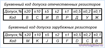
The most common resistors are issued with a tolerance of 5%, 10% and 20%. Precision resistors used in the measuring equipment have tolerances 0.1%, 0.2%, 0.5%, 1%, 2%. For example, at a resistor with a nominal resistance of 10 com and the tolerance of 10%, the actual resistance may be in the range from 9 to 11 kΩ ± 10%.
On the housing of the resistor, the tolerance is indicated after the nominal resistance and may consist of alphabetic code or digital value in percents.


Resistors with color marking tolerance indicates last Color ring: silver color - 10%, golden - 5%, red - 2%, brown - 1%, green - 0.5%, blue - 0.25%, purple - 0.1%. In the absence of an admission ring, the resistor has 20% tolerance.
1.3. Rated dispersion power.
The third important parameter of the resistor is its dispersion power
When the current passes through the resistor, electrical energy (power) in the form of heat is released on it, which first increases the temperature of the body of the resistor, and then due to heat transfer goes into the air. therefore dispersion capacity Called the greatest current of the current that the resistor is capable of withdrawing for a long time and dispel in the form of heat without prejudice to the loss of its nominal parameters.
Since too high the temperature of the body of the resistor can lead it to the failure, then when drafting the schemes, the value is set, which indicates the ability of the resistor to dispel one or another power without overheating.
Per unit measurement unit accepted watt (W).
For example. Suppose that through the resistor resistance 100 ohms flows the current 0.1 A, it means that the resistor dispels the power of 1 W. If the resistor is less power, it will quickly overheat and fail.
Depending on the geometric sizes Resistors can dispel a certain power, therefore resistors of different power differ in size: the greater the size of the resistor, the greater its rated power, the greater the current and voltage is able to withstand.
Resistors are available with dispersion capacity of 0.125 W, 0.25 W, 0.5 W, 1 W, 2 W, 3 W, 5 W, 10 W, 25 W and more.

On the resistors, starting with 1 W and above, the power value is indicated on the housing in the form of a digital value, while small-sized resistors have to be determined on the "eye".

With the acquisition of experience, the determination of the power of small-sized resistors does not cause any difficulty. Over the first time, as a reference point, you can use the usual match. Read more about power and additionally watch the video in the article.
However, with dimensions there is a small nuance, which must be taken into account when performing installation: the dimensions of domestic and foreign resistors of the same power are slightly different from each other - domestic resistors a little more of their foreign fellows.
Resistors can be divided into two groups: resistors permanent resistance (permanent resistors) and resistors aC resistance (variable resistors).
2. Resistors of constant resistance (permanent resistors).
The resistor is considered to be constant, the resistance of which in the process of work remains unchanged. Constructively, such a resistor is a ceramic tube, on the surface of which a conductive layer is applied, which has a certain ohmic resistance. At the edges of the tube, metal caps are pressed to which the conclusions of the resistor made from the irradiated copper wire are welded. From above, the casing of the resistor is covered with moisture-resistant color enamel.

Ceramic tube called resistive element and depending on the type of conductive layer applied to the surface, the resistors are divided into incomparable and wire.
Improvant resistors are used to work in electrical circuits of direct and alternating current, in which relatively small load currents flow. The resistor resistor is made in the form of fine semiconducting filmshown on the ceramic base.
Semiconductive film is called resistive layer and is made of a homogeneous substance film with a thickness of 0.1 - 10 μm (micrometer) or from microcompositions. Microcompositions can be made of carbon, metals and their alloys, from oxides and metal compounds, as well as in the form of a thicker film (50 μm) consisting of a crushed mixture of conductive substance.
Depending on the composition of the resistive layer, the resistors are divided into carbon, metal-plane (metallized), metalodielectric, metalloxic and semiconductor. Most wide use received metal and carbon composite permanent resistors. From the resistors of domestic production, mlt can be allocated, OMLT (metallized, lacquered enamel, heat-resistant), aircraft (carbon) and kim, yours (composite).

The incomplete resistors are distinguished by small size and mass, low cost, the possibility of using high frequencies to 10 GHz. However, they are not stable enough, since their resistance depends on temperature, humidity, applied load, duration of work, etc. But still the positive properties of inspire resistors are so significant that they received the greatest use.
2.2. Wire resistors.
Wire resistors are used in electrical circuits. direct current. In the manufacture of a resistor on its body into one or two layers, a thin wire made from nickeline, nichrome, constantan or other alloys with high electrical resistance is wedged. High resistivity of the wire allows you to perform a resistor with minimal consumption of materials and small sizes. The diameter of the used wires is determined by the density of the current passing through the resistor, technological parameters, reliability and cost, and begins with 0.03 - 0.05 mm.

To protect against mechanical or climatic influences and to fix the turns, the resistor is covered with varnishes and enamels or sealed. The type of insulation affects heat resistance, electrical strength and outer diameter of the wire: the larger the diameter of the wire, the thickness of the insulation layer and the higher the electrical strength.
The greatest application found wires in the enamel insulation of PE (enamel), PEV (high-strength enamel), PEV (heat-resistant enamel), PET (heat-resistant enamel), the advantage of which is a small thickness at sufficiently high electrical strength. Common resistors big power are wire enameled resistors of the type PEV, PEWT, C5-35, etc.

Compared with imbreak resistors, wires are characterized by higher stability. They can operate at higher temperatures, withstand significant overloads. However, they are more difficult in production, more expensive and affordable for use at frequencies above 1-2 MHz, as they have a high self-tank and inductance that appear already at frequencies in several kilohertz.
Therefore, they are mainly used in direct current or low-frequency circuits, where high accuracy and stability of work are required, as well as the ability to withstand significant overload currents causing significant overheating of the resistor.
With the advent of microcontrollers, modern technique has become more functional and at the same time with this much miniature. The use of microcontrollers made it possible to simplify the electronic circuits and thereby reduce current consumption by devices, which made it possible to miniature the element base. The figure below shows SMD resistors that are soldered on the board from the printed mounting.

On the concept schemes Permanent resistors, regardless of their type, are depicted as rectangleand the conclusions of the resistor are depicted in the form of lines conducted from the side of the rectangle. Such a designation is taken everywhere, but in some foreign circuits, the designation of the resistor in the shape of a toothed line (saws) is used.

Near conditional designation put the Latin letter " R.»And the sequence number of the resistor in the scheme, and also indicate its nominal resistance in the units of measurement of OM, whom, IOM.
Resistance value from 0 to 999 Ohm is denoted in omah, but the unit of measurement does not put:
15
- 15 Ohm.
680
- 680 Oh.
920
- 920 Oh.
On some foreign schemes for the designation of OM put the letter R.:
1R3 - 1.3 Ohm.
33r. - 33 Oh.
470r. - 470 Oh.
Resistance value from 1 to 999 comes are denoted killomakh With the addition of the letter " to»:
1.2k. - 1.2 com
10k. - 10 com
560K. - 560 com
Resistance value from 1000 kΩ and more denoted in units megaom With the addition of the letter " M.»:
1M - 1 MΩ
3.3m - 3.3 MΩ
56m - 56 MΩ

The resistor is used according to the power to which it is designed, and which can be withstanding without risk to be spoiled when the electric current is passed through it. Therefore, the schemes inside the rectangle prescribe symbols indicating the power of the resistor: the double oblique feature is denoted by the power of 0.125 W; a direct feature located along the resistor icon, denote the power of 0.5 W; Roman numbers are denoted by the power of 1 W and above.


4. Sequential and parallel compound of resistors.
Very often there is a situation when the resistor with the desired resistance does not appear when designing any device, but there are resistors with other resistances. Everything is very simple here. Knowing the calculation of the serial and parallel connection can be collected a resistor with any nominal.
For sequential Connection of resistors to their general resistance Robby Equal to the sum of all resistors connected to this chain:
Robry \u003d R1 + R2 + R3 + ... + Rn
For example. If R1 \u003d 12 com, and R2 \u003d 24 com, then their overall resistance Robbchsch \u003d 12 + 24 \u003d 36 com.

For parallel Connection of resistors Their overall resistance decreases and always less than the resistance of each individual resistor:
![]()
Suppose that R1 \u003d 11 com, and R2 \u003d 24 com, then their overall resistance will be equal to:
And the moment: with parallel connection of two resistors with the same resistance, their overall resistance will be equal to half of the resistance of each of them.

From the above examples it is clear that if you want to obtain a resistor with greater resistance, then a serial connection is used, and if with a smaller, then parallel. And if you have questions, read the article in which the connection methods are described in more detail.
Well, in addition to the read, see a video about resistors of constant resistance.
Well, in principle, and everything I wanted to say about the resistor in general and separately about resistors of permanent resistance. In the second part of the article we will get to know.
Good luck!
Literature:
V.I. Galkin - "Beginning Radio Affiner", 1989
V. A. Volga - "Details and nodes of radio-electronic equipment", 1977
V. G. Borisov - "Young Radio, 1992
Modern technique uses resistors with color marking. This creates some inconveniences for beginners in radio engineering. To learn the colors of the resistor to seek in the scatter, you need to use a table, or an online calculator determining the resistor rating. The proposed simplest device will help you easily determine the desired value.
The first two disks displaying numbers, these are:

The last disk that displays the multiplier is:

These discs are glued to plastic circles. To prevent erase of the inscriptions on paper was pasted scotch. Kreagashi with screws are fixed on a plastic basis. To lock the nuts used thermoclauses.

If you rarely enjoy this device, it is rational to perform it on a dense cardboard.
Practical useDetermination of the nominal resistor, knowing his colors
- We set the rollers so that the colors written on them coincided with three first stripes of the resistor.
- In the first two windows, the number (47) is obtained, it must be multiplied by the number in the last window (10). 47 * 10 \u003d 470 Ohm

There is a logical question - is it not easier to measure the resistance to the multimeter? Yes, easier, but there are exceptions. For example, when the resistor is faulty and cannot be measured by resistance, or when the resistor is installed on the board, and connected parallel resistance can be influenced.
Color definition, knowing the rating of the resistor
- For example, we need to find which bands will be on a resistor with a face value of 50 kiloma. Transfer 50 kilomes in ohm \u003d 50000 ohms
- In the windows with numbers exhibit 50.
- In the window with a multiplier, we put 10 at 3 degrees that when multiplying 5000 is equal to 50,000. Simply put, we attributed to 50 three zero.
- In the upper part of the rollers, colors will be written, which should be on a resistor with a par 50 kilome.

FAQ.
IN: Why do this fitness need, because it is easier to print the table on which the nominal value is determined, and it is even easier to calculate the program on the phone.
ABOUT: Print easier, and even easier to get confused, especially newcomer. Not everyone has a telephone that supports such a program, the more the phone can be discharged at the moment when it will most likely. This is an analog calculator.
IN: Which side of the resistor 1 band?
ABOUT: The first strip of the resistor is in the most extreme position than the other from the opposite side.
IN: What does the latest strip show?
ABOUT: The last bar shows the tolerance of the resistor nominal in the percentage ratio.
IN: The extreme stripes on my resistor are at the same distance from the ends, from which side then to start counting?
ABOUT: In this case, you need to pay attention to the tolerance bandwidth that is placed the latter. It usually happens brown, red, gold and silver color.
IN: On my resistor, not 4, and 5 bands. How to determine the rating of such a resistor?
ABOUT: Just like on a resistor with 4 bands, only the first three, and not two strips will indicate the number you need to multiply.
IN: All the time I confuse Omms and kiloma, every time you use the crib in the Internet kiloma in Omm.
ABOUT: Everything is very simple, - 1 ohms is one gram, 1 kilo is one kilogram. In 1 kilogram of 1000 grams, corresponds to 1 kilome of 1000 ohms.
IN: I am a full zero in mathematics and every time you have to use a calculator when multiplying, and this makes it necessary to fit uncomfortable.
ABOUT: In essence, it is not even necessary to multiply. If we see 10 to 4 degrees, then the number of four zero in the first two windows is needed.
Resistors are the most common elements of radio-electronic equipment and are used to regulate the current in electrical circuits.Resistance resistor - its main characteristic. The main unit of electrical resistance is OM (OM). In practice, derivatives are also used - kiloma (com), mega (IOM), gigam (GOM), which are associated with the main unit with the following ratios: 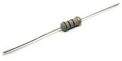 1 com \u003d 1000 ohm,
1 mom \u003d 1000 com
1 gom \u003d 1000 MΩ.
Resistors can be constant, that is, have unchanged resistance, and variables, that is, those whose resistance can be changed under certain limits. Resistors are available with certain values \u200b\u200bof resistance in a wide range from OM units to dozen.
Resistors of constant resistance
On concept diagrams next to the symbol of the resistor, the value of its resistance is affixed. Resistance less than kiloma is recorded as a number without measurement units; Resistance from one kiloma and above, but less than one megaoma, expressed in kiloma and clinging the letter "K" next to the figure; Resistance from one megaoma and above are recorded as a number by adding the letter "M". For example, 10 m (10 meg), 5.1 K (5.1 kiloma); 470 (470 Ohms); K68 (680 ohms).
The resistance value is usually indicated on the surface of the resistors. For labeling, small-sized resistors use alphanumeric code or color code consisting of colored stripes.
When using an alphanumeric resistance code, resistance are denoted by numbers indicating a measurement unit. It is customary to mark the letters: R - Ohm, K - Kiloma, M-M - Mr.
Deviation of the nominal resistors
Due to the imperfection of the technology of making resistors, their resistance may differ from the specified (nominal value) value. The industries produced wide-use resistors with a permissible deviation of the resistance of ± 5%, ± 10%, ± 20%. Therefore, along with the nominal value on the case and in the passport of resistors, the limits of permissible deviations are affixed. In this case, the recording of the form 12k ± 5% means that the nominal resistance value of the resistor is 12 com. The actual value may differ from the nominal, but not more than ± 0.6 com (by ± 5% of 12k).
When using the color labeling, the deviation of the resistor rating is denoted by a separate band (see table at the bottom of the article).
In the measuring radio-electronic devices, high precision resistors are used (the so-called precession resistors).
Power resistor
The thermal energy is released in the resistor when current flows, it dissipates from its surface into the surrounding space. However, if the power secreted in the resistor will be great, then heat from its surface will not have time to be done. The resistor will become overly heat and can even burn. Therefore, each resistor has a strictly defined maximum permissible value of the power that it is capable of dispel.
Power resistors It is usually recognized by their size (the greater the size of the resistor, the greater its power) or on the designation on the housings.
On the conceptual circuits, the power of the resistor used is usually indicated. The lack of indicating the power of the resistor means that negligible power is distinguished on it and any resistor with data resistance can be used.
Variable resistors
A variable resistor serves to smoothly regulate current and voltage.
Variable resistors are divided into adjustment and adjustable. Resistors with which they carry out various adjustments by changing their resistance are called variable resistors or potentiometers. Resistors, which change the resistance only during the device (settings) of the device, are called trimmed.
Variable resistors have three outputs, one of which is associated with moving contact, sliding along the surface of the conductive layer. The engine of the adjusting resistor is moved by hand by turning the protruding handle, triggering - a screwdriver inserted into the slot.
The resistance between any extreme output of the variable resistor and movable contact depends on the position of the engine.
The type of marking in which the paint is applied to the resistor body in the form of colored rings or points, is called color code. Each color corresponds to a specific digital value. The color marking on the resistors is shifted to one of the conclusions and reads from left to right. If, due to the small size of the resistor, the color label cannot be placed in one of the conclusions, then the first sign is made by a band wide twice as much as the rest.
The color labeling of foreign small-sized resistors common in Russia is most often of the four color rings. Rate of resistance determine the first three rings (two digits and multiplier). The fourth ring contains information about the permissible deviation of the resistance from the nominal value in percent.
In order not to confuse zero and the letter "O", "OM" often write the letter "Omega":

Time to decipher the color code of resistors can be significantly reduced if you use special
First of all, we will define the concept and designation of resistance as an electrical value. According to the theory, the resistance is a physical value that characterizes the properties of the conductor to prevent the passage of the electric current. In the international system of units (s), the unit of measuring the resistance is OM (Ω). For electrical engineering, this is a relatively small amount, so we will more often deal with kiloma (com) and megaoms (IOM). To do this, you need to learn the following sign:
1 com \u003d 1000 ohms;
1 Mom \u003d 1000 com;
And vice versa:
1 ohm \u003d 0.001 com;
1 com \u003d 0.001 MΩ;
Nothing difficult, but it is necessary to know it firmly.
Now about the nominal (values). Of course, the industry does not produce for radio amateurs of resistors with all rates. The manufacture of high-precision resistors is a labor-intensive matter and such resistors are used only in special high-precision equipment. You, for example, will not find in the usual resistor store for 1.9 com and at such accuracy most often no need - it is rarely needed, and if necessary, then there are rapid resistors for this.
The whole standard row with which we will face, I will not bring here - it is long enough and it is not worth it. Better learn to distinguish one resistor from the other. Marking devices can differently. The most convenient, in my opinion, was digital marking. She was done, for example, on the most running at one time resistors of the MLT type.
One glance at the resistor was enough to find out what he had resistance
For example, on the second top of the resistor, we read 2.2 and below K5%. The denomination of this resistor is 2.2 kiloma with an accuracy of 5%. For mega-resistors, "M" is used instead of "K" and Ohms are denoted by the letters "R", "E" or in general without a letter:
470 - 470 Ohm
18e - 18 ohm
Very often, any of the letters can stand instead of a comma:
2k2 - 2.2 kiloma
M15 - 0.15 mega or 150 kiloma
That's all the trick. Another parameter is the power of the resistor. The higher the power, the larger the current can withstand the resistor without destruction (combustion). Repeat back to the top drawing. Here, the resistors have the following power (from top to bottom) 2 W, 1 W, 0.5 watts, 0.25 W, 0.125 W. The first three are so great that they even had a place for labeling of power: MLT-2, MLT-1, MLT-0.5. The rest of the eye. Of course, they are issued (but most, alas, produced) and other types (and power) with "human" labeling, I will not list them, and they have the same principle.

PEVR-30, for example, looks like a decent size cylinder, but marked as well
But this fashion has almost moved, instead of the numbers appeared colored stripes and special codes and it will have to put up with it. 
What is this resistor and what is his nominal? To do this, you will have to refer to the special tables that I here and bring.