The choice of equipment on the example of lvs. Designing of a local area network for FE BelovTransAvto. Software and hardware
MINISTRY OF SCIENCE AND PROFESSIONAL EDUCATION
REPUBLIC OF SAKHA (YAKUTIA)
STATE EDUCATIONAL INSTITUTION
SECONDARY VOCATIONAL EDUCATION
NERUNGRINSKY HUMANITIES COLLEGE
Subject-cycle commission
"Mathematical disciplines and information technologies»
COURSE WORK
Organization of a local area network at an enterprise
Norvaishas Sergey Evgenievich
4th year student
Full-time form of education
Specialty: 230105.51
"Software
computers and automated systems "
Leader: Khamrilova L.A.
Protection date term paper:
"____" _______________ 2010
Grade: " "
Neryungri
Introduction 5
1.1. Purpose of packages and their structure 7
1.2. Exchange Control Methods 13
1.3. Traffic control in a star 15 network
Chapter 2. Networking Technology 18
2.1. Review and analysis of possible technologies for solving the task 18
Chapter 3. Designing an enterprise-wide network GOU SPO "Omsk College of Trade, Economics and Service" 22
3.1. Profile of the enterprise GOU SPO OKTEiS 22
3.2 Choosing network equipment 23
3.3 Brief description of the used network equipment 24
3.4 Choosing network software 25
3.4.1. Operating modes: 30
3.4.2 Installation and configuration 33
3.5. Schemes of the physical layout of the premises of OKTEiS 35
3.6. General scheme of the OKTEiS network 37
3.7. Theoretical and computational part 39
Conclusion 41
List of used literature 43
Introduction
If there are several computers in the same room, building or complex of nearby buildings, the users of which must jointly solve some problems, exchange data or use common data, then it is advisable to combine these computers into a local network.
A local network is a group of several computers connected by cables (sometimes also telephone lines or radio channels) used to transfer information between computers. Connecting computers to a local network requires network hardware and software.
The purpose of all computer networks can be summed up in two words: sharing (or sharing). First of all, I mean data sharing. People working on the same project have to constantly rely on data created by colleagues. Thanks to local network different people can work on one project not in turns, but simultaneously.
The local network provides the ability to share equipment. It is often cheaper to create a local network and install one printer for all departments than to purchase one printer for each workplace. The file server on the network allows you to share programs.
Hardware, software, and data are collectively referred to as resources. We can assume that the main purpose of a local network is access to resources.
The local network also has an administrative function. Monitoring the progress of projects on the network is easier than dealing with many stand-alone computers. If the classroom has a local network, then it also performs an administrative function, allowing you to monitor the progress of students' classes.
To communicate with external (peripheral) devices, the computer has ports through which it is able to transmit and receive information. It is easy to guess that if two or more computers are connected through these ports, they will be able to exchange information with each other. In this case, they form a computer network. If computers are located close to each other, use a common set of network equipment and are controlled by one software package, then such a computer network is called a local network. The simplest local area networks are used to serve workgroups. A working group is a group of people working on one project (for example, on the release of one magazine or on the development of one aircraft) or just employees of one department.
The aim of the course work is to design a local area network (LAN) for GOU SPO "Omsk College of Trade, Economics and Service" (OKTEiS).
To achieve the goal, the following tasks have been set:
analyze the methods of managing the exchange in the network;
review and analyze possible technologies for building a network;
select network equipment and software for LAN;
design general scheme College LAN;
Chapter 1. Packages, protocols and exchange control methods
Purpose of packages and their structure
Information in local networks, as a rule, is transmitted in separate chunks, chunks, called packets. Moreover, the maximum length of these packets is strictly limited (usually a few kilobytes). The length of the packet is also limited at the bottom (usually a few tens of bytes). The choice of bursting has several important considerations.
The local network, as already noted, must provide high-quality communication to all network subscribers. The most important parameter is the so-called access time, which is defined as the time interval between the moment the subscriber is ready to transmit (when he has something to transmit) and the moment the transmission starts. This is the time the subscriber waits for the start of his transmission. Naturally, it should not be too large, otherwise the value of the real, integral speed of information transfer between applications will greatly decrease even with high-speed communication.
Waiting for the start of transmission is due to the fact that several transmissions cannot occur simultaneously in the network (at least in the case of bus and ring topologies). There is always only one transmitter and one receiver (rarely, several receivers). Otherwise, information from different transmitters is mixed and distorted. In this regard, subscribers transmit their information in turn. And each subscriber, before starting the transfer, must wait for his turn. This waiting time for its turn is the access time.
If all the required information was transmitted by some subscriber at once, continuously, without dividing into packets, then this would lead to a monopoly seizure of the network by this subscriber for quite a long time. All other subscribers would have to wait for the end of the transfer of all information, which in some cases could take tens of seconds or even minutes (for example, when copying the contents of an entire hard disk). In order to equalize the rights of all subscribers, as well as to make approximately the same for all of them the value of the access time to the network and the integral speed of information transfer, packets of limited length are used.
Each packet, in addition to the actual data that needs to be transmitted, must contain a certain amount of service information. First of all, this is address information that determines from whom and to whom a given packet is transmitted.
Thus, the process of information exchange in the network is an interleaving of packets, each of which contains information transmitted from subscriber to subscriber.
Figure 1. Transmission of packets in the network between two subscribers.
In a particular case (Fig. 1), all these packets can be transmitted by one subscriber (when other subscribers do not want to transmit). But usually the network alternates packets sent by different subscribers (Fig. 2).

Figure 2. Transmission of packets in the network between several subscribers.
The structure and size of the packet in each network is strictly defined by the standard for this network and are primarily associated with the hardware features of this network, the selected topology and the type of information transmission medium. In addition, these parameters depend on the used protocol (order of information exchange).
But there are some general principles for forming the structure of the packet, which take into account the characteristic features of the exchange of information over any local area networks.
Most often, the package contains the following main fields or parts (Figure 3).

Figure 3. Typical package structure
A starting bit pattern or preamble that presets the adapter hardware or other network device to receive and process a packet. This field can be completely absent or reduced to a single start bit.
The network address (identifier) of the receiving subscriber, that is, an individual or group number assigned to each receiving subscriber in the network. This address allows the receiver to recognize a packet addressed to him personally, to the group he belongs to, or to all network subscribers at the same time (with broadcasts).
The network address (identifier) of the transmitting subscriber, that is, an individual number assigned to each transmitting subscriber. This address informs the receiving subscriber where the packet came from. The inclusion of the transmitter address in the packet is necessary when packets from different transmitters can alternately arrive at the same receiver.
Service information, which may indicate the type of packet, its number, size, format, route of its delivery, what the receiver needs to do with it, etc.
Data (data field) is the information for the transmission of which the packet is used. Unlike all other fields of the packet, the data field has a variable length, which, in fact, determines the total length of the packet. There are special control packages that do not have a data field. They can be thought of as network commands. Packages that include a data field are called information packets. Control packets can perform the function of starting and ending a communication session, acknowledging the receipt of an information packet, requesting an information packet, etc.
The checksum of a packet is a numerical code generated by the transmitter according to certain rules and containing information about the entire packet in a collapsed form. The receiver, repeating the calculations made by the transmitter with the received packet, compares their result with the checksum and makes a conclusion about the correctness or erroneousness of the packet transmission. If the packet is in error, then the receiver requests its retransmission. Typically a cyclic checksum (CRC) is used.
The stop combination serves to inform the equipment of the receiving subscriber about the end of the packet, provides the output of the receiver equipment from the receiving state. This field may be absent if a self-synchronizing code is used to determine when the packet has been transmitted.
Currently, experts and business representatives are the most effective way the creation of a unified information environment in the company recognized the construction of local networks. A local area network (LAN) is a group of computers connected to each other that can share common resources. Data is transmitted in the form of packets, and different technologies are used to control this process. On this moment the most demanded technology is Ethernet - a technology for transmitting data over a cable. The physical medium for the data transmission channel in wired network cables are used, usually twisted pair or fiber optic cable. Single information space in the company, it is necessary for its employees - network users - to be able to quickly exchange data, share a variety of resources and devices, and perform many other actions necessary for the successful implementation of its core business.
Key benefits of local area networks for business:
Ensuring continuous access of the company's personnel to common resources - documents, databases, etc., which saves time and ensures a high level of employee communication;
The ability to share office equipment - printers, faxes, scanners, copiers, allowing you to save on the purchase additional devices;
Simplicity and ease of moving and adding jobs and equipment, which reduces the cost and time of company personnel;
Increase the security of critical business information through the use of data protection systems.
ALP Group specialists carry out work on the organization and construction of switched local networks, using modern technologies and their own serious experience accumulated over many years of creation, maintenance and technical support engineering systems for domestic business. Creation of a local network is a responsible process that requires a high degree of professional training and skill level. Indeed, the stable operation of the entire company depends on the stability of the LAN.

Basic requirements for a local area network
Ease of management
Adaptation for the most popular types of cables and devices
Availability of spare channels and potential for subsequent expansion and optimization

Stages of building computer networks
1. Development. It includes a survey of the territory on which it is supposed to build a local network, a discussion with the client of the tasks that it will perform, the formation of technical specifications and the choice of equipment.
2. Installation and. At this stage, the cable is laid, after which the installation and subsequent configuration of the equipment, software and data protection system is carried out.
3. Testing. The LAN is being checked for its performance, stability, security and compliance with accepted norms and quality standards.
4. Warranty and post-warranty service. Providing support and carrying out preventive and repair works of the network and equipment.

The exchange of information in a LAN occurs according to certain rules, which are called protocols. Different protocols describe different sides of the same type of communication. At the same time, taken together, they form a protocol stack. Workstations that are connected to a local network can be interconnected in several ways. The configuration of a network or the method of connecting its elements is usually called a topology. Experts identify three main schemes for combining computers when building a local-computer network - "star", "common bus" and "ring".
"Star". It is the most common. When using topology, each node (separate work station) connects to the LAN using its own cable, one connector of which connects to the network adapter and the other to the hub.
Operating a network based on this principle provides an enterprise with several important benefits:
A fairly low cost of adding new jobs (up to about 1,000 units);
Independent operation of computers: if one of them fails, the rest will continue to work.
It should be borne in mind that the star topology also has its drawbacks. If the hub turns out to be faulty, then the stations connected to it will also not be able to work. Also, when creating a local network according to the "star" type, a cable route of considerable length may be required.
"Common bus". A topology in which information flows through workstations connected in parallel to the backbone (main cable). However, the data on request is received only by the addressee having the IP address from which the information was requested. The inconvenience of this principle of organizing a local-computer network can be considered the fact that if the connection of one PC with the backbone is broken, all the rest will fail. It is worth considering the fact that a "shared bus" configuration may not always be able to meet the increased requirements of an enterprise to the level of LAN performance.
"Ring". It is a method of serially connecting PCs with each other and transmitting a one-way signal in a circle. In fact, every PC repeats and amplifies the signal, transmitting it further over the network. This scheme also has its drawback: if one workstation fails, the entire network will be stopped. Also worth noting are the limitations of the total length. However, a significant advantage of this topology can be considered optimal balancing of the equipment load and convenience when laying cables.
Most suitable for LAN organization the topology is always selected individually. The main selection criteria are the specific needs of a particular company. A very commonly used scheme is a combination of various topologies. For example, a snowflake configuration is used in high-rise buildings. With this principle of creating a local network, it is necessary to use file servers for different workgroups of the company and a common central server.

LAN Features
At enterprises, local networks are characterized by the organization of working groups - combining several personal computers into one group with a single name. Network administrators are responsible for the smooth operation of the LAN as a whole or some of its sections. In complex networks, the administrator's rights are strictly regulated, and the actions of each member of the network administrators group are recorded.
The creation of a local network is most often carried out on the basis of Ethernet technology. To organize simple networks, routers, modems, switches and network adapters are used. In ordinary local area networks, it is customary to use static or dynamic routing.
LAN construction usually involves the use of technology from the two original layers of the OSI network model - channel or physical. Their functionality is sufficient to carry out work within one of the most common topologies - "ring", "star" or "common bus". PCs used in building corporate network, can support protocols or more high level... Other protocols can be installed and used at the nodes of the network, but the functions performed with their help will no longer be directly related to the LAN.
ALP Group specialists will carry out the whole range of works on creating a local network of your company using modern technologies and observing all international standards - with high quality and in optimal terms.
Introduction
Modern society has entered a post-industrial era, which is characterized by the fact that information has become essential resource development of the economy and society. In line overall development high technologies, the main contribution to the informatization of all spheres of life is made by computer technologies.
One of characteristic features the current stage of development of information technology can be defined by the words "unification" or "integration". Analog and digital, telephone and computer are combined, speech, data, audio and video signals are combined in one stream, technique and art (multimedia and hypermedia) are combined into a single technology. The flip side of this process is “sharing” or “sharing”. An integral part of this process is the development of computer networks.
Computer networks are essentially distributed systems. The main feature of such systems is the presence of multiple data centers. Computer networks, also called computing networks, or data transmission networks, are the logical result of the evolution of two most important scientific and technical branches of modern civilization - computer and telecommunication technologies. On the one hand, networks are special case distributed computing systems in which a group of computers consistently performs a group of interrelated tasks, exchanging data in an automatic mode. On the other hand, computers and data multiplexing have evolved in various telecommunication systems.
A local area network (LAN) or LAN is a group of personal computers or peripheral devices interconnected by a high-speed data link in the location of one or many nearby buildings. The main task that is posed in the construction of local area networks is the creation of the company's telecommunications infrastructure, which ensures the solution of the assigned tasks with the greatest efficiency. There are a number of reasons for combining individual personal computers on a LAN:
First, resource sharing allows multiple PCs or other devices to share a separate disk(file-server), DVD-ROM drive, printers, plotters, scanners and other equipment, which reduces costs for each individual user.
Second, in addition to the sharing of expensive peripheral devices, LVL allows similar use of network versions of application software.
Thirdly, the LAN provides new forms of user interaction in one team, for example, working on a common project.
Fourthly, LANs make it possible to use common means of communication between different application systems (communication services, data and video data transmission, speech, etc.).
There are three principles of LAN:
1) Openness, the ability to connect additional computers and other devices, as well as communication lines (channels) without changing the hardware and software of existing network components.
2) Flexibility - preservation of performance when the structure changes as a result of failure of any computer or communication line.
3) Efficiency ensuring the required quality of service for users at minimal cost.
A local area network has the following distinctive features:
High data transfer speed (up to 10 GB), high bandwidth;
Low transmission errors (high quality transmission channels);
Effective high-speed data exchange control mechanism;
The exact number of computers connected to the network. At present, it is difficult to imagine any organization without a local network installed in it, all organizations are striving to modernize their work with the help of local networks.
This course project describes the creation of a local network based on Gigabit Ethernet technology, by connecting several houses, and the organization of Internet access.
1. Creation of a local area network
1.1 Network topologies
Topology is a way of physically connecting computers to a local area network.
There are three main topologies used in the construction of computer networks:
Bus topology;
Star topology;
Ring topology.
When creating a network with the "Bus" topology, all computers are connected to one cable (Figure 1.1). Terminators should be located at its ends. This topology is used to build 10 Megabit 10Base-2 and 10Base-5 networks. Coaxial cables are used as the cable.

Figure 1.1 - Topology "Bus"
Passive topology is based on the use of one common communication channel and its collective use in a time-sharing mode. Violation of a common cable or any of the two terminators leads to the failure of the network section between these terminators (network segment). Disconnecting any of the connected devices has no effect on the operation of the network. Failure of the communication channel destroys the entire network. All computers on the network "listen" to the carrier and do not participate in the transfer of data between neighbors. The throughput of such a network decreases with increasing load or with an increase in the number of nodes. Active devices - repeaters with an external power supply can be used to connect pieces of the bus.
The "Star" topology assumes that each computer is connected with a separate wire to a separate port of a device called a hub or repeater (repeater), or a hub (Hub) (Figure 1.2).

Figure 1.2 - "Star" topology
Hubs can be either active or passive. If there is a disconnection between the device and the hub, the rest of the network continues to work. True, if this device was the only server, then the work will be somewhat difficult. If the hub fails, the network will stop working.
This network topology is most convenient when searching for damage to network elements: cable, network adapters or connectors. When adding new devices, the "star" is also more convenient than the topology of the common bus. You can also take into account that 100 and 1000 Mbit networks are built according to the "Star" topology.
Ring topology is an active topology. All computers on the network are connected in a vicious circle (Figure 1.3). Routing cables between workstations can be difficult and costly if they are not in a ring but, for example, in a line. Twisted pair or fiber optic is used as a carrier in the network. Messages circulate in a circle. A workstation can transfer information to another workstation only after it receives the right to transfer (token), so collisions are excluded. Information is transmitted around the ring from one workstation to another, therefore, if one computer fails, if no special measures are taken, the entire network will fail.
The transmission time of messages increases in proportion to the increase in the number of nodes in the network. There are no restrictions on the diameter of the ring, because it is determined only by the distance between nodes in the network.
In addition to the above network topologies, the so-called. hybrid topologies: star-bus, star-ring, star-star.

Figure 1.3 - Topology "Ring"
In addition to the three considered basic, basic topologies, the network topology "tree" is often used, which can be considered as a combination of several stars. As with a star, a tree can be active, or true, and passive. With an active tree, central computers are located in the centers of combining several communication lines, and with a passive tree, hubs (hubs).
Combined topologies are also used quite often, among which the most widespread are star-bus and star-ring. A star-bus topology uses a combination of a bus and a passive star. In this case, both individual computers and entire bus segments are connected to the hub, that is, in fact, it is implemented physical topology A "bus" that includes all computers on the network. In this topology, several hubs can also be used, interconnected and forming a so-called backbone bus. In this case, separate computers or bus segments are connected to each of the hubs. Thus, the user can flexibly combine the advantages of bus and star topologies, as well as easily change the number of computers connected to the network.
In the case of a star-ring topology, not the computers themselves are united into a ring, but special hubs, to which computers are connected using star-shaped double communication lines. In reality, all computers on the network are included in a closed loop, since all communication lines inside the hubs form a closed loop. This topology allows you to combine the benefits of star and ring topologies. For example, hubs allow you to collect all the connection points of the cables in a network in one place.
This course project will use a star topology, which has the following advantages:
1. failure of one workstation does not affect the operation of the entire network as a whole;
2. good scalability of the network;
3. easy troubleshooting and network breaks;
4. high network performance (subject to correct design);
5. flexible administration options.
1.2 Cable system
The choice of cabling is dictated by the type of network and the selected topology. The physical characteristics of the cable required by the standard are laid down during its manufacture, as evidenced by the markings applied to the cable. As a result, today almost all networks are designed on the basis of UTP and fiber-optic cables, coaxial cable is used only in exceptional cases, and then, as a rule, when organizing low-speed stacks in wiring closets.
Today, only three types of cables are laid in projects of local computer networks (standard):
coaxial (two types):
Thin coaxial cable
Thick coaxial cable.
twisted pair (two main types):
Unshielded twisted pair (UTP);
Shielded twisted pair (STP).
fiber optic cable (two types):
Multimode cable (fiber optic cable multimode);
Single mode cable (fiber optic cable single mode).
Not long ago, coaxial cable was the most common type of cable. This is due to two reasons: first, it was relatively inexpensive, lightweight, flexible and easy to use; secondly, widespread popularity coaxial cable has made it safe and easy to install.
The simplest coaxial cable consists of a copper core, insulation surrounding it, a braided metal shield and an outer jacket.
If the cable, in addition to the metal braid, has a layer of "foil", it is called a double-screened cable (Figure 1.4). In the presence of strong interference, you can use a cable with a quadruple shielding, it consists of a double layer of foil and a double layer of metal braiding.

Figure 1.4 - Coaxial cable structure
The braid, called the shield, protects the data transmitted over the cables by absorbing external electromagnetic signals, called interference or noise, so the shield does not allow interference to distort the data.
Electrical signals are transmitted through the conductor. A core is a single wire or bundle of wires. The core is usually made of copper. The conductor and the metal braid must not touch, otherwise a short circuit will occur and noise will distort the data.
Coaxial cable is more noise-resistant, signal attenuation in it is less than in twisted pair.
Attenuation is the decrease in signal strength as it travels through the cable.
Thin coaxial cable is a flexible cable with a diameter of about 5 mm. It is applicable to almost any type of network. Connects directly to the network adapter card using a T-connector.
The connectors on the cable are called BNC connectors. The thin coaxial cable is capable of transmitting the signal at a distance of 185 m, without its delayed attenuation.
Thin coaxial cable belongs to a group called the RG-58 family. The main distinguishing feature of this family is the copper core.
RG 58 / U - solid copper conductor.
RG 58 / U - twisted wires.
RG 58 C / U - military standard.
RG 59 - Used for broadband transmission.
RG 62 - Used in Archet networks.
A thick coaxial cable is a relatively rigid cable with a diameter of about 1 cm. It is sometimes called the Ethernet standard because this type of cable was designed for a given network architecture. The copper core of this cable is thicker than that of a thin cable, so it carries signals further. A special transceiver device is used to connect to a thick cable.
The transceiver is equipped with a special connector called a "vampire tooth" or piercing coupler. It penetrates the insulating layer and comes into contact with the conductive core. To connect the transceiver to the network adapter, connect the transceiver cable to the AUI-port connector on the network card.
A twisted pair is two insulating copper wires twisted around each other. There are two types of thin cable: unshielded twisted pair (UTP) and shielded twisted pair (STP) (Figure 1.5).

Figure 1.5 - Unshielded and shielded twisted pair
Several twisted pairs often placed in a single containment. Their number in such a cable may vary. Curling wires allows you to get rid of electrical noise induced by neighboring pairs and other sources (motors, transformers).
Unshielded twisted pair (10 Base T specification) is widely used in LAN, the maximum segment length is 100m.
The unshielded twisted pair consists of 2 insulated copper wires. There are several specifications that regulate the number of turns per unit of length, depending on the purpose of the cable.
1) Traditional telephone cable, which can only transmit speech.
2) A cable capable of transmitting data at speeds up to 4 Mbps. Consists of 4 twisted pairs.
3) A cable capable of transmitting data at speeds up to 10 Mbps. Consists of 4 twisted pairs with 9 turns per meter.
4) A cable capable of transmitting data at speeds up to 16 Mbps. Consists of 4 twisted pairs.
5) A cable capable of transmitting data at speeds up to 100 Mbps. Consists of 4 twisted copper wire pairs.
One potential problem with all types of cables is crosstalk.
Crosstalk is crosstalk caused by signals on adjacent wires. Unshielded twisted pair cables are particularly affected by this interference. To reduce their influence, a screen is used.
Shielded twisted pair (STP) cable has a copper braid that provides greater protection than unshielded twisted pair cable. Pairs of STP wires are wrapped in foil. As a result, the shielded twisted pair has excellent isolation, protecting the transmitted data from external interference.
Consequently, STP is less susceptible to electrical interference than UTP and can transmit signals at higher speeds and over long distances.
To connect a twisted pair to a computer, telephone connectors RG-45 are used.

Figure 1.6 - Structure of fiber optic cable
In a fiber optic cable, digital data is propagated along optical fibers in the form of modulated light pulses. This is a relatively reliable (secure) method of transmission, since no electrical signals are transmitted. Therefore, fiber optic cable cannot be hidden and data intercepted, from which any cable conducting electrical signals is not immune.
Fiber-optic lines are designed to move large amounts of data at very high speeds, since the signal in them is practically not attenuated or distorted.
An optical fiber is an extremely thin glass cylinder called a core, covered with a layer of glass called a cladding, with a different refractive index than the core (Figure 1.6). Sometimes fiber is made from plastic, it is easier to use, but has inferior performance compared to glass.
Each glass fiber transmits signals in only one direction, so the cable consists of two fibers with separate connectors. One of them is used for signal transmission, the other for reception.
Transmission over fiber optic cable is not subject to electrical interference and is carried out at an extremely high speed (currently up to 100 Mbit / s, theoretically possible speed is 200000 Mbit / s). It can transmit data over many kilometers.
This course project will use Category 5E Twisted Pair and Fiber Optic Cable.
1.3 Gigabit Ethernet Network Technology
When organizing the interaction of nodes in local networks, the main role is assigned to the link layer protocol. However, in order for the data link layer to cope with this task, the structure of local networks must be quite definite, for example, the most popular data link layer protocol - Ethernet - is designed for parallel connection of all network nodes to a common bus for them - a piece of coaxial cable. This approach of using simple structures of cable connections between computers in a local area network was in line with the main goal set by the developers of the first local area networks in the second half of the 70s. This goal was to find a simple and cheap solution for combining several dozen computers located within the same building into a computer network.
This technology has lost its practicality, since now not dozens, but hundreds of computers located not only in different buildings, but also in different districts, are connected to local networks. Therefore, we choose a higher speed and reliability of information transmission. These requirements are met by Gigabit Ethernet 1000Base-T technology.
Gigabit Ethernet 1000Base-T is based on twisted pair and fiber optic cable. Since Gigabit Ethernet is compatible with 10 Mbps and 100Mbps Ethernet, it is easy to migrate to this technology without investing heavily in software, cabling, and training.
Gigabit Ethernet is an extension of IEEE 802.3 Ethernet that uses the same packet structure, format and support for CSMA / CD, full duplex, flow control, and more, while delivering a theoretical 10x performance improvement.
CSMA / CD (Carrier-Sense Multiple Access with Collision Detection) is a technology for multiple access to a common transmission medium in a local computer network with collision control. CSMA / CD refers to decentralized random methods... It is used both in conventional networks such as Ethernet and in high-speed networks ( Fast Ethernet, Gigabit Ethernet).
Also called network protocol which uses the CSMA / CD scheme. The CSMA / CD protocol operates at the data link layer in the OSI model.
The characteristics and areas of application of these popular in practice networks are related precisely to the peculiarities of the access method used. CSMA / CD is a modification of the "clear" Carrier Sense Multiple Access (CSMA).
If, while transmitting a frame, the workstation detects another signal occupying the transmission medium, it stops transmission, sends a jam signal, and waits for a random amount of time (known as a "backoff delay" and found with the truncared binary exponential backoff algorithm) before send the frame again.
Collision detection is used to improve CSMA performance by interrupting transmission immediately after collision detection and reducing the likelihood of a second collision during retransmission.
Collision detection methods vary depending on the equipment used, but on electrical buses such as Ethernet, collisions can be detected by comparing transmitted and received information. If it differs, then another transmission is superimposed on the current one (there was a collision) and the transmission is interrupted immediately. A jam signal is sent, which delays the transmission of all transmitters for an arbitrary time interval, reducing the likelihood of collisions during retry.
1.4 Hardware
The choice of hardware should be given special attention, the possibility of expanding the system and the ease of its modernization play a significant role, since this is what allows to provide the required performance not only at the current time, but also in the future.
Of greatest interest is the maximum amount of RAM that can be used on this server, the ability to install more powerful processor, as well as a second processor (if you plan to use an operating system that supports a dual-processor configuration). The question of what configuration of the disk subsystem can be used on this server is also important, first of all, what is the volume of disks, the maximum number of them.
There is no doubt that a vital parameter of any server is its high-quality and uninterrupted power supply. In this regard, it is necessary to check that the server has several (at least two) power supplies. Usually these two power supplies work in parallel, i.e. if it fails, the server continues to work, receiving power from another (serviceable) power supply. In this case, there should also be the possibility of their "hot" replacement. And, needless to say, an uninterruptible power supply is needed. Its presence allows, in the event of a power outage, at least to correctly shut down the operating system and turn on the server.
High reliability of servers is achieved by implementing a set of measures related to both ensuring the necessary heat exchange in the case, controlling the temperature of the most important components, monitoring a number of other parameters, and fully or partially duplicating subsystems.
It is also necessary to pay attention to the selection of additional hardware components of the network. When choosing network equipment, it is worth considering the network topology and the cabling system on which it is executed.
· The level of equipment standardization and its compatibility with the most common software tools;
· Speed of information transfer and the possibility of its further increase;
· Possible network topologies and their combinations (bus, passive star, passive tree);
· Method of control of exchange in the network (CSMA / CD, full duplex or marker method);
· Permitted types of network cable, its maximum length, immunity from interference;
· Cost and technical characteristics of specific hardware (network adapters, transceivers, repeaters, hubs, switches).
Minimum server requirements:
CPU AMD Athlon64 X2 6000+ 3.1GHz;
Dual NC37H network adapters with TCP / IP Offload Engine network card;
RAM 8 GB;
HDD 2x500 GB Seagate Barracuda 7200 rpm.
1.5 Software
Computer networks software consists of three components:
1) stand-alone operating systems (OS) installed on workstations;
2) network operating systems installed on dedicated servers, which are the basis of any computer network;
3) network applications or network services.
As a stand-alone operating system for workstations, as a rule, modern 32-bit operating systems are used - Windows 95/98, Windows 2000, Windows XP, Windows VISTA.
The following are used as network operating systems in computer networks:
NetWare OS from Novell;
Microsoft network operating systems (Windows NT, Microsoft Windows 2000 Server, Windows Server 2003, Windows Server 2008)
Windows Server 2008 provides three main benefits:
1) Improved control
Windows Server 2008 allows you to better control your server and network infrastructure and focus on solving your top priority problems by:
Simplified IT infrastructure management with new tools that provide a single interface for configuring and monitoring servers and the ability to automate routine operations.
Streamline and manage Windows Server 2008 installation and management by deploying only the roles and features you need. Configuring servers reduces vulnerabilities and reduces the need for software updates, resulting in easier ongoing maintenance.
Proactively identify and resolve problems with powerful diagnostics that provide a visual insight into the current state of your server environment, both physical and virtual.
Better control over remote servers such as branch office servers. By streamlining server administration and data replication, you can better serve your users and eliminate some of the management headaches.
Easily manage your web servers with Internet Information Services 7.0, a powerful web platform for applications and services. This modular platform has a simpler task-based management interface and integrated Web service state management, tight control over host interactions, and a number of security enhancements.
Better control of user settings with Advanced Group Policy.
2) Increased flexibility
The following features in Windows Server 2008 enable you to create flexible and dynamic datacenters that meet your ever-changing business needs.
Embedded technologies for virtualization on one server of several operating systems (Windows, Linux, etc.). With these technologies, and simpler, more flexible licensing policies, you can now easily take advantage of the benefits of virtualization, including the economics.
Centralized application access and seamless integration of remotely published applications. In addition, it should be noted that it is possible to connect to remote applications via firewall without using a VPN - this allows you to quickly respond to the needs of users, regardless of their location.
Wide choose new deployment options.
Flexible and functional applications connect workers to each other and to data, thus enabling visibility, sharing and processing of information.
Interaction with the existing environment.
A developed and active community for support throughout the life cycle.
3) Improved protection
Windows Server 2008 strengthens the security of the operating system and the environment in general, creating a solid foundation on which you can grow your business. Windows Server protects servers, networks, data, and user accounts from failure and intrusion through the following.
Enhanced security features reduce the vulnerability of the server core, thereby increasing the reliability and security of the server environment.
Network access protection technology can isolate computers that do not meet the requirements of current security policies. The ability to enforce security compliance is a powerful means of protecting your network.
Enhanced intelligent rule and policy writing solutions that improve the manageability and security of network functions enable the creation of policy-driven networks.
Data protection that allows access only to users with the proper security context and prevents loss in the event of a hardware failure.
Anti-malware protection with User Account Control with a new authentication architecture.
Increased system resilience, reducing the likelihood of loss of access, work results, time, data and control.
For users of local area networks, a set of network services is of great interest, with the help of which he gets the opportunity to view a list of computers on the network, read a remote file, print a document on a printer installed on another computer on the network, or send a mail message.
The implementation of network services is carried out by software (software tools). The file and print services are provided by the operating systems, while the rest of the services are provided by the network application or applications. Traditional network services include: Telnet, FTP, HTTP, SMTP, POP-3.
The Telnet service allows you to organize user connections to the server using the Telnet protocol.
The FTP service provides file transfers from Web servers. This service is provided by web browsers ( Internet Explorer, Mozilla Firefox, Opera, etc.)
HTTP is a service designed to view Web pages (Web sites), provided by network applications: Internet Explorer, Mozilla Firefox, Opera, etc.
SMTP, POP-3 - incoming and outgoing e-mail services. Implemented by mail applications: Outlook Express, The bat and etc.
An antivirus program is also required on the server. ESET NOD32 Smart Security Business Edition is a new, integrated solution that provides comprehensive server and workstation protection for all types of organizations.
This solution includes antispam and personal firewall functions that can be used directly on the workstation.
ESET NOD32 Smart Security Business Edition provides support for file Windows servers, Novell Netware and Linux / FreeBSD and their protection against known and unknown viruses, worms, Trojans and spyware as well as other internet threats. The solution includes on-access scanning, on-demand scanning and automatic updates.
ESET NOD32 Smart Security Business Edition includes ESET Remote Administrator, which provides updates and centralized administration in corporate network environments or WANs. The solution provides optimal performance for systems and networks while reducing bandwidth consumption. The solution has functionality and the flexibility that any company needs:
1) Installation on the server. Version for corporate clients ESET NOD32 Smart Security can be installed both on the server and on workstations. This is especially important for companies seeking to maintain their competitiveness, as servers are as vulnerable to attacks as normal workstations. If the servers are not protected, a single virus can damage the entire system.
2) Remote administration. With ESET Remote Administrator, you can monitor and administer your security software solution from anywhere in the world. This factor is of particular importance for geographically distributed companies, as well as for system administrators who prefer to work remotely or are on the move.
Possibility of "Mirror". The ESET NOD32 Mirror feature allows the IT administrator to limit network bandwidth by creating an internal update server. As a result, ordinary users do not need to go online to receive updates, which not only saves resources, but also reduces the overall vulnerability of the information structure.
1.6 Brief network plan
Table 1.1 - Brief equipment summary
2 Physical construction of a local network and organization of Internet access
2.1 Network equipment
2.1.1 Active equipment
In this course project, the following equipment will be used:
D-link DGS-3200-16 switch;
D-link DGS-3100-24 switch;
D-link DFL-1600 router;
Converter 1000 Mbit / s D-Link DMC-810SC;
Server IBM System x3400 M2 7837PBQ.

Figure 2.1 - D-link DGS-3200-16 switch
General characteristics
Device type switch
there is
Number of slots for additional
interfaces 2
Control
Console port there is
Web interface there is
Telnet support there is
SNMP support there is
Additionally
IPv6 support there is
Standards support Auto MDI / MDIX, Jumbo Frame, IEEE 802.1p (Priority tags), IEEE 802.1q (VLAN), IEEE 802.1d (Spanning Tree), IEEE 802.1s (Multiple Spanning Tree)
Dimensions (WxHxD) 280 x 43 x 180 mm
Number of ports 16 x Ethernet 10/100/1000
switch Mbps
32 Gbps
MAC address table size 8192
Router
IGMP v1

Figure 2.2 - D-link DGS-3100-24 switch
General characteristics
Device type switch
Rack mountable there is
Number of slots for additional interfaces 4
Control
Console port there is
Web interface there is
Telnet support there is
SNMP support there is
Additionally
Standards support Auto MDI / MDIX, Jumbo Frame, IEEE 802.1p (Priority tags), IEEE 802.1q (VLAN), IEEE 802.1d (Spanning Tree), IEEE 802.1s (Multiple Spanning Tree)
Dimensions (WxHxD) 440 x 44 x 210 mm
The weight 3.04 kg
Additional Information 4 combo 1000BASE-T / SFP ports
Number of ports 24 x Ethernet 10/100/1000
switch Mbps
Stack support there is
Internal bandwidth 68 Gbps
MAC address table size 8192
Router
Dynamic routing protocols IGMP v1

Figure 2.3 - D-link DFL-1600 router
General characteristics
Device type router
Control
Console port there is
Web interface there is
Telnet support there is
SNMP support there is
Additionally
Standards support IEEE 802.1q (VLAN)
Dimensions (WxHxD) 440 x 44 x 254 mm
Additional Information 6 user configurable Gigabit Ethernet ports
Number of ports 5 x Ethernet 10/100/1000
switch Mbps
Router
Firewall there is
NAT there is
DHCP server there is
Dynamic protocols
routing IGMP v1, IGMP v2, IGMP v3, OSPF
VPN Tunnel Support yes (1200 tunnels)

Figure 2.4 - Converter 1000 Mbit / s D-Link DMC-805G
General characteristics
· One channel of media conversion between 1000BASE-T and 1000BASE-SX / LX (SFP mini GBIC transceiver);
· Compatible with IEEE 802.3ab 1000BASE-T, IEEE802.3z 1000BASE-SX / LX Gigabit Ethernet standards;
· Status indicators on the front panel;
LLCF support (Link Loss Carry Forward, Link Pass Through);
· Supports duplex and auto-negotiation for optical port;
DIP switch for setting Fiber (auto / manual), LLR (Enable / Disable);
· Support LLR (Link Loss Return) for FX port;
· Use as a stand-alone device or installation in the DMC-1000 chassis;
· Monitoring duplex / channel status for both types of environments through the DMC-1002 control module when installed in the DMC-1000 chassis;
· Forced setting of the duplex mode, LLR on / off for FX, ports on / off through the DMC-1002 control module of the DMC-1000 chassis;
· Data transmission at channel speed;
· Hot swap when installed in the chassis;
Dimensions (edit) 120 x 88 x 25 mm
The weight 305 BC
Working temperature 0 ° to 40 ° C
Storage temperature -25 ° to 75 ° C
Humidity 10% to 95% non-condensing

Figure 2.5 - Server IBM System x3400 M2 7837PBQ
Server characteristics
CPU Intel Xeon Quad-Core
Series E5520
Processor frequency a 2260 MHz
Number of processors 1 (+1 optional)
System bus frequency 1066 MHz
Second level cache (L2C) 8 Mb
Chipset Intel 5500
RAM size 12 Gb
Maximum RAM 96 Gb
RAM slots 12
RAM type DDR3
Chipset video Built in
Video memory size 146 Mb
Quantity hard drives 3
Hard disk size 0 Gb
Maximum number of disks 8
Hard disk controller M5015
Optical drives DVD ± RW
Network interface 2x Gigabit Ethernet
External I / O ports 8хUSB ports (six external, two internal), dual-port
Mounting type Tower
Power supply type 920 (x2) W
Maximum amount
power supplies 2
Dimensions (edit) 100 x 580 x 380 mm
The weight 33 kg
Guarantee 3 years
Additional Information Keyboard + Mouse
Additional accessories (ordered separately) Servers IBM System x3400 M2 7837PBQ
2.1.2 Passive equipment
Passive equipment constitutes the physical infrastructure of networks (patch panels, sockets, racks, enclosures, cables, cable channels, trays, etc.). The bandwidth and quality of communication channels largely depend on the quality of the cable system, therefore, complex and expensive equipment under the control of qualified personnel in this area should be used to test physical data carriers.
2.2 Calculation of the cable system
2.2.1 Calculation of the length of the fiber-optic cable of the main trunk
In the course project, you need to connect 4 houses. Because the given floors are 5th, 12th and 14th, then it is more expedient to lead the main fiber-optic cable through overhead communications.
A special self-supporting fiber-optic cable is used to suspend the main highway between the poles and buildings, which has a central power element (CSE) and a steel cable. The optimum distance between the cable support supports is from 70 to 150 meters.

Figure 2.5 - Location of houses
Table 2.1 - Calculation of the length of the fiber-optic cable of the main trunk
| Cable section | Length, m | Number of segments | Length with a margin, m |
| 1-2 | 105 | 1 | 136,5 |
| 2-3 | 75 | 1 | 97,5 |
| 3-4 | 190 | 1 | 247 |
| 4-5 | 100 | 1 | 130 |
| 5-6 | 75 | 1 | 97,5 |
| Total | 708,5 | ||
2.2.2 Calculation of Twisted Pair Length
Cable risers are used to lay the cable through the floors. In the entrances. In the entrances, the cable does not need to be packed, because the entrances are not so dirty and the threats of a sharp temperature drop and pollution are minimal.
The twisted pair from the switch on the roof to the desired floor goes along the riser without any protection, from the electrical panel to the apartment, both in cable ducts and without them, simply attached to the wall with brackets.
The server and the router are located in house No. 2 on the 5th floor of the 3rd entrance in a sealed room with a constant temperature maintenance of no more than 30 ° C.
Table 2.2 - Calculation of the length of the twisted pair in houses
| Distance from switch to hole in |
Number of cables per apartment, m |
Length-on with a reserve, m | ||||||||||
| 2 | 52 | 55 | 58 | 63 | 56 | 51 | 48 | 15 | 4 | 7 | 1952 | 2537,6 |
| 5 | 34 | 30 | 38 | 28 | 26 | - | - | 15 | 4 | 5 | 924 | 1201,2 |
| 7 | 42 | 45 | 48 | 53 | 46 | 41 | 38 | 15 | 4 | 7 | 1672 | 2173,6 |
| 8 | 34 | 30 | 38 | 28 | 26 | - | - | 15 | 5 | 5 | 1155 | 1501,5 |
| 5703 | 7413,9 | |||||||||||
2.3 Logical network structuring
When the switch is operating, the data transmission medium of each logical segment remains common only for those computers that are directly connected to this segment. The switch connects the data transmission media of various logical segments. It transfers frames between logical segments only when necessary, that is, only when the communicating computers are in different segments.
Dividing a network into logical segments improves network performance if the network contains groups of computers that primarily communicate with each other. If there are no such groups, then the introduction of switches into the network can only worsen the overall performance of the network, since deciding whether to transfer a packet from one segment to another requires additional time.
However, even in a medium-sized network, such groups, as a rule, are available. Therefore, dividing it into logical segments gives a performance gain - traffic is localized within groups, and the load on their shared cabling systems is significantly reduced.
Switches decide which port to send a frame to by analyzing the destination address placed in the frame, as well as based on information about the belonging of a computer to a particular segment connected to one of the switch ports, that is, based on information about the network configuration ... In order to collect and process information about the configuration of the segments connected to it, the switch must go through the "learning" stage, that is, do some preliminary work on its own to study the traffic passing through it. Determination of the belonging of computers to segments is possible due to the presence in the frame of not only the destination address, but also the address of the source that generated the packet. Using source address information, the switch maps port numbers to computer addresses. In the process of studying the network, the bridge / switch simply transmits the frames that appear at the inputs of its ports to all other ports, working as a repeater for some time. After the bridge / switch learns that the addresses belong to the segments, it starts transmitting frames between ports only in the case of inter-segment transmission. If, after training is complete, a frame with an unknown destination address suddenly appears at the switch input, then this frame will be repeated on all ports.
Bridges / switches that work in this way are usually called transparent, since the appearance of such bridges / switches in the network is completely invisible to its end nodes. This avoids changing their software when moving from simple configurations using only hubs to more complex, segmented configurations.
There is another class of bridges / switches that transfer frames between segments based on complete information about the inter-segment route. This information is written into the frame by the station-source of the frame, therefore, such devices are said to implement the source routing algorithm. When using bridges / switches with source routing, end nodes must be aware of the division of the network into segments and network adapters, in which case they must have a component in their software that deals with the choice of the route of frames.
For the simplicity of the principle of operation of a transparent bridge / switch, you have to pay with restrictions on the topology of a network built using devices of this type - such networks cannot have closed routes - loops. The bridge / switch cannot function properly on a looped network, causing the network to become clogged with looping packets and degrading performance.
A Spanning Tree Algorithm (STA) has been developed to automatically recognize loops in a network configuration. This algorithm allows bridges / switches to adaptively build a link tree as they learn the link topology of segments using special test frames. When closed loops are detected, some links are declared redundant. The bridge / switch can only use the backup link if a primary link fails. As a result, networks built on the basis of bridges / switches that support the spanning tree algorithm have a certain margin of safety, but it is impossible to improve performance by using multiple parallel links in such networks.
2.4 IP addressing on the network
There are 5 classes of IP addresses - A, B, C, D, E. The belonging of an IP address to a particular class is determined by the value of the first octet (W). The following shows the correspondence between the values of the first octet and the address classes.
Table 2.3 - Range of octets of IP address classes
The IP addresses of the first three classes are designed to address individual nodes and individual networks. Such addresses consist of two parts - the network number and the node number. This scheme is similar to the postcode scheme - the first three digits encode the region, and the rest are the post office within the region.
The advantages of a two-tier scheme are obvious: it allows, firstly, to address entirely separate networks within a concatenated network, which is necessary to ensure routing, and secondly, to assign numbers to nodes within one network independently of other networks. Naturally, computers belonging to the same network must have IP addresses with the same network number.
IP addresses of different classes differ in the bit depth of the network and host numbers, which determines their possible range of values. The following table summarizes the main characteristics of Class A, B, and C IP addresses.
Table 2.4 - Characteristics of IP - addresses of classes A, B and C
For example, the IP address 213.128.193.154 is a class C address, and belongs to node 154 on the 213.128.193.0 network.
The addressing scheme, defined by classes A, B, and C, allows data to be sent either to a single node or to all computers on a single network (broadcast). However, there is network software that needs to broadcast data to a specific group of nodes, not necessarily on the same network. In order for programs of this kind to function successfully, the addressing system must provide for the so-called group addresses. Class D IP addresses are used for these purposes. The Class E address range is reserved and is not currently used.
Along with the traditional decimal form of notation of IP addresses, the binary form can also be used, which directly reflects the way the address is represented in the computer memory. Since an IP address is 4 bytes long, it is represented in binary as a 32-bit binary number (that is, a sequence of 32 zeros and ones). For example, the address 213.128.193.154 in binary form is 11010101 1000000 11000001 10011010.
IP assumes the presence of addresses, which are treated in a special way. These include the following:
1) Addresses, the value of the first octet of which is equal to 127. Packets sent to such an address are not actually transmitted to the network, but processed by the software of the sending node. Thus, a node can forward data to itself. This approach is very convenient for testing network software in conditions where there is no way to connect to the network.
2) Address 255.255.255.255. A packet whose destination is 255.255.255.255 should be sent to all nodes on the network in which the source is located. This type of broadcast is called limited broadcast. In binary form, this address is 11111111 11111111 11111111 11111111.
3) Address 0.0.0.0. It is used for business purposes and is interpreted as the address of the node that generated the packet. Binary representation of this address 00000000 00000000 00000000 00000000
Additionally, addresses are interpreted in a special way:
The scheme for dividing an IP address into a network number and a node number, based on the concept of an address class, is rather rough, since it involves only 3 options (classes A, B, and C) for distributing the address digits under the corresponding numbers. Consider the following situation as an example. Let's say that some company connecting to the Internet has only 10 computers. Since the smallest possible number of nodes are class C networks, this company should have received a range of 254 addresses (one class C network) from the organization dealing with the allocation of IP addresses. The disadvantage of this approach is obvious: 244 addresses will remain unused, since they cannot be allocated to computers of other organizations located in other physical networks. If the organization in question had 20 computers distributed over two physical networks, then it would have to be allocated a range of two class C networks (one for each physical network). In this case, the number of "dead" addresses will double.
For a more flexible definition of the boundaries between the digits of the network and host numbers within the IP address, so-called subnet masks are used. A subnet mask is a special type of 4-byte number that is used in conjunction with an IP address. The "special kind" of the subnet mask is as follows: the bits of the mask corresponding to the bits of the IP address reserved for the network number contain ones, and the bits corresponding to the bits of the host number contain zeros.
Paired with an IP address, a subnet mask eliminates the need for address classes and makes the entire IP addressing system more flexible.
So, for example, the mask 255.255.255.240 (11111111 11111111 11111111 11110000) allows you to split the range of 254 IP addresses belonging to the same class C network into 14 ranges that can be allocated to different networks.
For the standard division of IP addresses into network number and host number, defined by classes A, B, and C, subnet masks are of the form:
Table 2.5 - Class A, B and C subnet masks
|
Class |
Binary form |
Decimal form |
| 11111111 00000000 00000000 00000000 | 255.0.0.0 | |
| 11111111 11111111 00000000 00000000 | 255.255.0.0 | |
| 11111111 11111111 11111111 00000000 | 255.255.255.0 |
Since each node on the Internet must have a unique IP address, it is certainly important to coordinate the allocation of addresses to individual networks and nodes. This coordinating role is played by The Internet Corporation for Assigned Names and Numbers (ICANN).
Naturally, ICANN does not solve the problem of allocating IP addresses to end users and organizations, but is engaged in the allocation of address ranges between large organizations providing Internet access services (Internet Service Providers), which, in turn, can interact with both smaller providers. and with end users. So, for example, ICANN delegated functions for the allocation of IP addresses in Europe to the RIPE Coordination Center (RIPE NCC, The RIPE Network Coordination Center, RIPE - Reseaux IP Europeens). In turn, this center delegates part of its functions to regional organizations. In particular, Russian users are served by the Regional Network Information Center "RU-CENTER".
In this network, the allocation of IP addresses is performed using the DHCP protocol.
DHCP provides three ways to allocate IP addresses:
1) Manual distribution. In this method, the network administrator maps the hardware address (usually the MAC address) of each client computer to a specific IP address. In fact, this method of address allocation differs from manual setting each computer only because the address information is stored centrally (on the DHCP server), and therefore easier to change if necessary.
2) Automatic distribution. With this method, each computer is allocated an arbitrary free IP address from the range specified by the administrator for permanent use.
3) Dynamic allocation. This method is similar to automatic allocation, except that the address is given to the computer not for permanent use, but for a certain period. This is called leasing an address. After the expiration of the lease, the IP address is again considered free, and the client is obliged to request a new one (however, it may turn out to be the same).
IP addresses in the course project are taken from class B and have a mask of 225.225.0.0. Issued by DHCP with binding to the MAC address to avoid illegal connections.
Table 2.6 - Assignment of subnets
| House number | Number of entrances | Floor number | Subnet address |
| 2 | 4 | 5 | |
| 5 | 4 | 4 | |
| 7 | 4 | 10 | |
| 8 | 5 | 11 |
2.5 Organization of Internet access via satellite
2.5.1 Types of satellite Internet
Two-way satellite Internet means receiving data from a satellite and sending it back also via satellite. This method is very high quality, since it allows you to achieve high speeds during transmission and sending, but it is quite expensive and requires obtaining permission for radio transmitting equipment (however, the latter is often taken over by the provider).
One-way satellite Internet means that the user has some existing method of connecting to the Internet. As a rule, this is a slow and / or expensive channel (GPRS / EDGE, ADSL connection where Internet access services are poorly developed and limited in speed, etc.). Only requests to the Internet are transmitted through this channel. These requests go to the node of the operator of one-way satellite access (various technologies of VPN connection or traffic proxying are used), and the data received in response to these requests is transmitted to the user via a broadband satellite channel... Since most users get their data primarily from the Internet, this technology allows for faster and cheaper traffic than slow and expensive terrestrial connections. The volume of outgoing traffic over a terrestrial channel (and hence the cost of it) becomes quite modest (the outgoing / incoming ratio is about 1/10 when surfing the web, from 1/100 or better when downloading files).
Naturally, it makes sense to use one-way satellite Internet when the available terrestrial channels are too expensive and / or slow. In the presence of inexpensive and fast "terrestrial" Internet, satellite Internet makes sense as a backup connection option in case of loss or poor performance of "terrestrial".
2.5.2 Equipment
The core of the satellite Internet. Carries out the processing of data received from the satellite, and the extraction of useful information. There are many different types cards, but the most famous are the cards of the SkyStar family. The main differences of DVB cards today are the maximum data rate. Also, the characteristics include the ability to decode the signal hardware, software support for the product.
There are two types of satellite dishes:
· Offset;
· Direct focus.
Direct focus antennas are a "saucer" with a circular section; the receiver is located directly opposite its center. They are more difficult to set up than offset ones and require ascent to the satellite angle, which is why they can “collect” atmospheric precipitation. Offset antennas, due to the displacement of the focus of the "dish" (point of maximum signal), are installed almost vertically, and therefore easier to maintain. The antenna diameter is selected in accordance with the weather conditions and the signal strength of the required satellite.
The converter acts as a primary converter, which converts the microwave signal from the satellite into an intermediate frequency signal. Most converters are nowadays adapted to prolonged exposure to moisture and UV rays. When choosing a converter, you should mainly pay attention to the noise figure. For normal work it is worth choosing converters with a value of this parameter in the range of 0.25 - 0.30 dB.
To implement the two-way method, a transmitting card and a transmitting converter are added to the required equipment.
2.5.3 Software
There are two complementary approaches to the implementation of software for satellite Internet.
In the first case, the DVB card is used as a standard network device(but working only for reception), and a VPN tunnel is used for transmission (many providers use PPTP ("Windows VPN"), or OpenVPN at the client's choice, in some cases an IPIP tunnel is used), there are other options. This disables control of packet headers in the system. The request packet goes to the tunnel interface, and the response comes from the satellite (if you do not disable header control, the system considers the packet to be an error (in the case of Windows - not so)). This approach allows you to use any application, but has a high latency. Most satellite providers available in the CIS (SpaceGate (Itelsat), PlanetSky, Raduga-Internet, SpectrumSat) support this method.
The second option (sometimes used in conjunction with the first): the use of special client software, which, due to the knowledge of the protocol structure, makes it possible to speed up the receipt of data (for example, a web page is requested, the server views it from the provider and immediately, without waiting for a request, sends pictures from this pages, assuming that the client will request them anyway; the client side caches such responses and returns them immediately). Such client side software usually acts as an HTTP and Socks proxy. Examples: Globax (SpaceGate + others on request), TelliNet (PlanetSky), Sprint (Raduga), Slonax (SatGate).
In both cases, it is possible to "share" traffic over the network (in the first case, sometimes you can even have several different subscriptions of a satellite provider and share a dish due to special configuration of a machine with a dish (requires Linux or FreeBSD, under Windows requires third-party software)).
Some providers (SkyDSL) necessarily use their software (playing the role of both a tunnel and a proxy), often also performing client shaping and preventing sharing Satellite Internet between users (also preventing the use of anything other than Windows as an OS).
2.5.4 Advantages and Disadvantages
The following advantages of satellite Internet can be distinguished:
The cost of traffic in the hours of least capacity utilization
Independence from land lines (when using GPRS or WiFi as a request channel)
High final speed (reception)
· The ability to watch satellite TV and "fishing from the satellite"
The ability to freely choose a provider
Disadvantages:
The need to purchase special equipment
The complexity of installation and configuration
Generally lower reliability compared to ground connection (more components needed for smooth operation)
The presence of restrictions (direct visibility of the satellite) on the installation of the antenna
· High ping (delay between sending a request and receiving a response). This is critical in some situations. For example, when working in the interactive mode Secure Shell and X11, as well as in many multi-user online systems (the same SecondLife cannot work at all via satellite, Counter Strike shooter, Call of Duty - works with problems, etc.)
If there are at least pseudo-unlimited tariff plans(like "2000 rubles for 40 Gb for 512 kbps further - unlim but 32 kbps" - TP Active-Mega, ErTelecom, Omsk) terrestrial Internet is already becoming cheaper. With the further development of cable infrastructure, the cost of terrestrial traffic will tend to zero, while the cost of satellite traffic is strictly limited by the cost of launching a satellite and its reduction is not planned.
When working through some operators, you will have a non-Russian IP-address (SpaceGate Ukrainian, PlanetSky - Cypriot, SkyDSL - German), as a result of which services that are used for some purpose (for example, we start up only from the Russian Federation) determine the user's country, will not work correctly.
· The software part is not always "Plug and Play", in some (rare) situations it can be difficult and it all depends on the quality of the operator's technical support.
The course project will use two-way satellite Internet. This will allow achieving high data rates and high-quality packet transmission, but will increase the project implementation costs.
3. Safety when working at height
Work at height is considered to be all work that is performed at a height of 1.5 to 5 m from the surface of the ground, floor or working floor, on which work is performed from mounting devices or directly from structural elements, equipment, machines and mechanisms, during their operation, installation and repair.
Persons who have reached 18 years of age are allowed to work at heights, who have a medical certificate of admission to work at heights, who have been trained and instructed in safety precautions and who have received admission to independent work.
Work at heights must be carried out from scaffolding (scaffolding, scaffolding, flooring, platforms, telescopic towers, suspended cradles with winches, ladders and other similar auxiliary devices and devices) that ensure safe working conditions.
All paving means used to organize workplaces at height must be registered, have inventory numbers and plates indicating the date of the conducted and the next tests.
Laying of decks and work on random supports (boxes, barrels, etc.) is prohibited.
Control over the condition of the paving means should be carried out by persons from among the engineers and technicians who are appointed by an order for the enterprise (oil depot).
Workers of all specialties, to perform even short-term work at a height from stairs, must be provided with safety belts and, if necessary, protective helmets.
Safety belts issued to workers must be labeled with a test mark.
It is prohibited to use a defective harness or with an expired test period.
Work at heights is done during the day.
In emergency cases (when troubleshooting), on the basis of an order from the administration, work at a height at night is permitted in compliance with all safety rules under the supervision of engineering personnel. The place of work should be well lit at night.
In winter, when working outdoors, paving equipment should be systematically cleaned of snow and ice and covered with sand.
With a wind force of 6 points (10-12 m / s) or more, with a thunderstorm, heavy snowfall, icy conditions, work at a height in the open air is not allowed.
Do not arbitrarily rebuild decking, scaffolds and fences.
Electric wires located closer than 5 m from the stairs (scaffolds) must be protected or de-energized while the work is being performed.
Workers are obliged to perform the assigned work, observing the labor protection requirements set out in this instruction.
For violation of the requirements of the instructions relating to the work they perform, workers are liable in the manner prescribed by the Internal Regulations.
Simultaneous production of work in 2 or more tiers vertically is prohibited.
Do not fold the tool near the edge of the platform, or throw it and materials on the floor or on the ground. The tool should be kept in a special bag or box.
It is forbidden to throw any objects for feeding to the worker at the top. The feeding should be done using ropes, to the middle of which the necessary items are tied. The other end of the rope should be in the hands of the worker standing below, who keeps the objects being lifted from swinging.
Anyone working at heights must ensure that there are no people underneath his workplace.
When using ladders and stepladders, it is prohibited:
· Work on unreinforced structures and walk on them, as well as climb over fences;
· Work on the top two rungs of the ladder;
· Be two workers on a ladder or on one side of a stepladder;
· Move up the stairs with a load or with a tool in hand;
· Use stairs with steps sewn with nails;
· Work on a faulty staircase or on the steps doused with slippery oil products;
· Build up stairs in length, regardless of the material from which they are made;
· Stand or work under the stairs;
· Install ladders near rotating shafts, pulleys, etc .;
· Perform work with a pneumatic tool;
· To carry out electric welding works.
4. Economic costs of building a local network
This course project implies the following economic costs.
Table 4.1 - List of economic costs *
| Name | Units | Qty |
per unit (rub.) |
Amount (rub) |
| Fiber-optic cable EKB-DPO 12 | m | 708,5 | 36 | 25506 |
| FTP cable 4 pairs cat.5e<бухта 305м>Exalan + - | bay | 25 | 5890 | 147250 |
| D-Link DGS-3200-16 switch | PCS | 2 | 13676 | 27352 |
| D-Link DGS-3100-24 switch | PCS | 5 | 18842 | 94210 |
| D-link DFL-1600 router | PCS | 1 | 71511 | 71511 |
| IBM System x3400 M2 7837PBQ Server | PCS | 1 | 101972 | 101972 |
| APC SUA2200I Smart-UPS 2200 230V UPS | PCS | 2 | 29025 | 58050 |
| RJ-45 connectors | Pack (100pcs) | 3 | 170 | 510 |
| MT-RJ connectors | PCS | 16 | 280 | 4480 |
| Server cabinet | PCS | 1 | 2100 | 2100 |
| Router cabinet | PCS | 1 | 1200 | 1200 |
| Switch cabinet | PCS | 7 | 1200 | 8400 |
| D-Link DMC-805G Converter | PCS | 16 | 2070 | 33120 |
| Satellite dish + DVB card + converter | PCS | 1 | 19300 | 19300 |
| Staples 6mm | Pack (50 pcs) | 56 | 4 | 224 |
| Total | 595185 | |||
Economic costs do not include cost installation works... Cables and connectors are rated with a margin of ~ 30%. Prices are indicated at the time of creation of the course project, including VAT.
Conclusion
In the process of developing the course project, a LAN was created in a residential area, which has access to global network... An informed choice of the type of network was made based on consideration of many options. Expansion of the network is envisaged for its further growth.
In the course design, class B IP addresses were used, since there are one hundred and one workstations on the network. The assignment of addresses was carried out by the DHCP protocol. The entrance number was used as the subnet address.
The point for calculating the required amount of equipment contains data and calculations of the equipment used. The development cost is 611,481 rubles. All calculated parameters meet the criteria for network performance.
A short network plan has been drawn up, where all the characteristics of the equipment used are indicated. The Power Tool Safety section explains how to handle a power tool and how to work safely with it.
In general, the course project contains all the necessary data for building a local area network.
List of sources used
1.http: //www.dlink.ru;
2.http: //market.yandex.ru;
3.http: //www.ru.wikipedia.org.
4. Computer networks. Training course [Text] / Microsoft Corporation. Per. from English - M .: "Russian edition" LLP "Channel Trading Ltd.", 1998. - 696s.
5. Maksimov, N.V. Computer networks: Tutorial[Text] / N.V. Maksimov, I.I. Popov - M .: FORUM: INFRA-M, 2005 .-- 336p.
The choice of topology is determined, in particular, by the layout of the room in which the LAN is deployed. In addition, the costs of purchasing and installing network equipment are of great importance, which is an important issue for the company, the range of prices here is also quite large.
3.1. Enterprise LAN topology
For the LAN of the enterprise under consideration, the most optimal is the star topology due to the fact that it is a more productive structure: each computer, including the server, is connected by a separate cable segment to a central hub.
The main advantage of such a network is its resistance to failures arising from malfunctions on individual PCs or due to damage to the network cable.
The most important characteristic of information exchange in local networks is the so-called access methods, which regulate the order in which a workstation gains access to network resources and can exchange data.
Since the CSMA / CD method has proven itself well in small and medium networks, this method is convenient for the enterprise in question. In addition, the Ethernet network architecture, which will be used by the enterprise network, uses this method of access.
A network based on a twisted pair cable, unlike a network based on a thin and thick coaxial cable, is built in a star topology. To build a network according to the specified topology, a larger amount of cable is required (but the cost of a twisted pair is low). This scheme also has an invaluable advantage - high fault tolerance. Failure of one or more workstations does not lead to failure of the entire system. True, if a hub fails, its failure will affect all devices connected through it.

Another advantage this option is the simplicity of expanding the network, since when using additional concentrators (up to four in series), it becomes possible to connect a large number of workstations (up to 1024). When using unshielded twisted pair (UTP), the segment length between the hub and the workstation should not exceed 100 m. This condition is met for the enterprise in question.
3.2. Network resources
The next important aspect of network design is the sharing of network resources (printers, faxes, modems and other peripherals).
The listed resources can be used both in peer-to-peer networks and in networks with a dedicated server. However, in the case of a peer-to-peer network, its shortcomings are immediately apparent. To work with the listed components, they need to be installed on a workstation or connected to it peripherals... When this station is turned off, all components and corresponding services become unavailable for collective use.
In networks with a dedicated server, workstations have 24/7 access to the network periphery, since the server never shuts down, except for short stops for maintenance.
The enterprise has four printers - one in each department. Let's consider the issue of connecting the printer to a LAN. There are several ways to do this:
- connection to a workstation. The printer is connected to the workstation that is closest to it. As a result, this workstation becomes a print server. The disadvantage of such a connection is that when performing print jobs, the performance of the workstation decreases for some time, which negatively affects the operation of application programs with intensive use of the printer. In addition, if the machine is turned off, the print server will become inaccessible to other nodes;
- direct connection to the server. The printer is connected to the parallel port of the server using a special cable. In this case, it is constantly available for all workstations. The disadvantage of such a solution is due to the limitation on the length of the printer cable, which ensures correct data transfer. Although the cable can be extended for 10 m or more, it should be laid in ducts or in ceilings, which increases the cost of organizing the network;
- connection to the network through a special network interface. The printer is equipped with a network interface and connects to the network like a workstation. The interface card acts as a network adapter, and the printer registers itself with the server as a LAN node. The server software transfers print jobs over the network directly to the connected network printer;
- connection to a dedicated print server. An alternative to the previous option is to use specialized print servers. Such a server is a network interface, arranged in a separate case, with one or more connectors (ports) for connecting printers. However, in this case, using a print server is impractical.
In this example, due to the fact that installing a separate print server increases the cost of creating a network (as well as purchasing a printer with a network interface), it is advisable to connect printers directly to workstations in departments. This decision is also supported by the fact that the printers are located in those premises where the need for them is greatest. Therefore, the first method of connecting the printer was chosen.
4. Development and description of the enterprise LAN
4.1. Construction scheme
The LAN is built in a star topology, although, to be more precise, it is a tree: all network clients are branches of the central "trunk" channel. But topologically, the entire network is a star with the center in the form of a hub in the server room of the information and technical support department.
4.2. Main administrative blocks
Organizing computers into workgroups has two important benefits for network administrators and users. The first, the most important, is that the domain servers constitute (form) a single administrative unit that shares the security service and information on the user's account cards. Each working group has one database containing user and group account cards, as well as settings for the security system.
The second benefit concerns user convenience: when users browse the network for available resources, they see domains, not servers and printers scattered across the network.
4.3. Server configuration
Network operating system runs on the server. On the other hand, client computers can run different operating systems. For the client's operating system to use the network, special drivers must be installed to enable the client computer's network interface card to communicate with the network. These drivers work in a similar way to printer drivers that allow application programs send information to the printer. Software network driver enables programs to send and receive information over the network. Each computer on a network can contain one or more network interface cards that connect the computer to the network.
Obviously, the performance of a LAN depends on the computer used as the server. When using Windows 2000 Server, you need to focus on the fastest computer. There is a choice between ready-made servers offered by manufacturers and suppliers of computer equipment, and servers self assembly... If you have a certain experience, a server that is independently assembled to order can make up an alternative to the finished product. Therefore, you should pay attention to a number of issues discussed below.
When asked about the bus used, the answer is unambiguous - PCI. Besides the fact that PCI components have high performance (due to the 64-bit bus width), they also allow software configuration. Due to the latter circumstance, possible conflicts between connected hardware resources are almost always automatically prevented.
Windows 2030 Server has high memory requirements from the start. Therefore, taking into account the fact that the cost of RAM today is not so high, it is not advisable to make the minimum amount of RAM less than 512 MB (both from the point of view of price and from the point of view of performance).
It is recommended to use Fast SCSI hard drives and an appropriate SCSI adapter in servers. When using Fast SCSI, the data transfer speed reaches 10 Mbps. Newest hard drives with Ultra SCSI interface have transfer rates up to 20 Mbps. If the win-chester is to work even faster, you need to install a more expensive Ultra Wide SCSI disk and a corresponding controller. The Ultra Wide SCSI drive has a transfer rate of up to 40 Mbps, making it ideal for high-performance server environments, including high-volume networks. However, for the enterprise in question, it is better to use ordinary IDE hard drives, since the use of SCSI significantly increases the cost of the server.
A small case is contraindicated for such a computer, as it can lead to overheating, especially when using a high-performance processor and multiple hard drives. The ideal case would be a Big Tower case, among other things, providing the possibility of further expansion of the system. Even more convenient are special server cases equipped with powerful blocks power supply, additional fans, removable blanks and a protective front panel. If the server will be equipped with two or more hard disks, you need to think about additional cooling. For this, special fans are used, which can be additionally installed in the system unit.
Since all workstations connected to the network will constantly access the server, one of its most important components is a powerful 32-bit Network Card... It must effectively manage information exchange, i.e. have a coprocessor that takes over the main functions central processing unit processing incoming data to the server.
Thus, a LAN topology has been developed for a small enterprise, and the use of a specific server OS has been justified.
An example of a development approach Enterprise LAN... Part 2| 2011-11-24 04:05:14 | Super User | Local network | https: //site/media/system/images/new.png | In the final part of the article, we will consider the main stages of building a local computer network of an enterprise, we will get acquainted with the concept of topology of computer networks | network topology, local network topology, computer network topology, network resources, use of network resources
Large companies have in circulation a large amount of data of a different nature:
- text files;
- graphic;
- Images;
- tables;
- schemes.
It is important for the management that all information has a convenient format, is easily converted and transferred in any medium to the right hands. But paper documents have long begun to be replaced by digital ones, since a computer can contain a lot of data, which is much more convenient to work with through process automation. This is also facilitated by the transfer of information, reports and contracts to partners or review companies without lengthy travel.
This is how the need arose for the ubiquitous supply of departments of firms with electronic computing devices. At the same time, the question arose of combining these devices into a single complex for the protection, safety and convenience of moving files.
In this article we will tell you how to facilitate the design of a local area network (computer) network in the enterprise.
What is a LAN, its functions
This is a connecting connection of a number of computers into one enclosed space. This method is often used in large companies, in production. You can also create a small connection of 2 - 3 devices yourself, even at home. The more inclusions in the structure, the more complex it becomes.
Types of networking
There are two types of connection, they differ in complexity and the presence of a leading, central link:
- Equal.
- Multilevel.
Equivalent, they are peer-to-peer, are characterized by the similarity in technical specifications... They have the same distribution of functions - each user can get access to all common documents, perform the same operations. Such a scheme is easy to operate and does not require many efforts to create it. The downside is its limitedness - no more than 10 members can enter this circle, otherwise the overall efficiency of work and speed are violated.
Server-side design of a company's local network is more laborious, however, such a system has a higher level of information protection, and there is also a clear distribution of responsibilities within the web. The best in terms of technical characteristics (powerful, reliable, with greater RAM) the computer is assigned by the server. This is the center of the entire LAN, all data is stored here, from the same point you can open or terminate access to documents for other users.
Functions of computer networks
The main properties that need to be taken into account when drawing up a project:
- Possibility of connecting additional devices. Initially, the grid may contain several machines; with the expansion of the company, an additional inclusion may be required. When calculating power, you should pay attention to this, otherwise you will need to do redevelopment and buy new ones expendable materials increased strength.
- Adaptation for different technologies. It is necessary to ensure the flexibility of the system and its adaptability to different network cables and different software.
- Availability of backup lines. First, it refers to the exit points of ordinary computers. In the event of a failure, it should be possible to connect another cord. Second, you need to ensure that the server is running smoothly when there is a tiered connection. This can be done by automatically failing over to the second hub.
- Reliability. Equipping with uninterruptible power supplies, autonomous energy reserves to minimize the possibility of communication interruption.
- Protection from extraneous influences and hacking. Stored data can be protected not just with a password, but with a whole bunch of devices: hub, switch, router and remote access server.
- Automated and manual control. It is important to install a program that will analyze the state of the grid at every moment of time and notify about faults for quick fixing. An example of such software is RMON. In this case, you can also use personal monitoring via Internet servers.
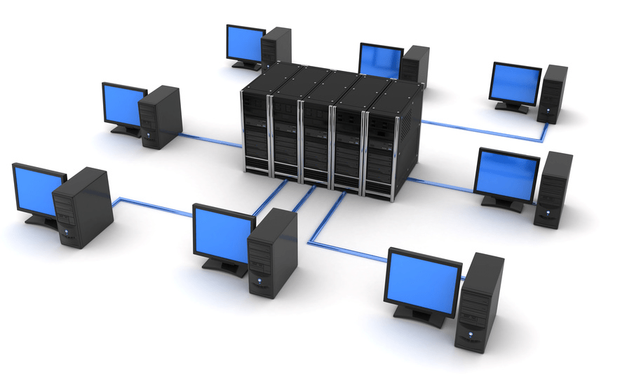
Drawing up technical requirements for the design and calculation of a local area network (LAN) at an enterprise
The properties give rise to conditions that must be taken into account when drawing up a project. The entire design process begins with the preparation of a technical assignment (TOR). It contains:
- Information security standards.
- Providing all connected computers with access to information.
- Performance parameters: response time from a user request to opening the desired page, throughput, that is, the amount of data in work and the transfer delay.
- Reliability conditions, that is, the readiness of long-term, even constant work without interruptions.
- Replacement of component parts - expansion of the grid, additional connections or installation of equipment of a different power.
- Support for different types of traffic: text, graphics, multimedia content.
- Providing centralized and remote control.
- Integration different systems and software packages.
When the TK is drawn up in compliance with the needs of users, the type of inclusion of all points in one network is selected.
Basic LAN Topologies
These are ways of physically connecting devices. The most frequent ones are represented by three figures:
- tire;
- ring;
- star.
Busbar (linear)
During the assembly, one lead cable is used, from which wires already go to user computers. The main cord is directly connected to the server that stores the information. It also selects and filters data, provides or restricts access.

Advantages:
- An outage or problem with one item does not disrupt the rest of the grid.
- Designing an organization's local area network is fairly straightforward.
- Relatively low cost of installation and consumables.
Disadvantages:
- A failure or damage to the carrier cable stops the entire system from working.
- A small area can be connected in this way.
- Performance can suffer from this, especially if the connection passes between more than 10 devices.
"Ring" (annular)
All user computers are connected in series - from one device to another. This is often done in the case of peer-to-peer LANs. In general, this technology is used less and less.

Advantages:
- No cost for hub, router and other networking equipment.
- Several users can transmit information at once.
Disadvantages:
- The transfer rate across the entire grid depends on the power of the slowest processor.
- In case of cable malfunctions or in the absence of connection of any element, the general work stops.
- Setting up such a system is difficult.
- When connecting an additional workplace, it is necessary to interrupt the general activity.
"Star"
This is a parallel connection of devices to a network to a common source - a server. A hub or hub is most often used as a cent. All data is transferred through it. In this way, not only computers can work, but also printers, faxes and other equipment. In modern enterprises, this is the most frequently used method of organizing activities.

Advantages:
- Easy to connect one more site.
- Performance does not depend on the speed of individual elements, therefore it remains at a stable high level.
- Just find a breakdown.
Disadvantages:
- A malfunction of the central unit stops all users' activities.
- The number of connections is determined by the number of ports on the server device.
- The mesh consumes a lot of cable.
- Expensive equipment.
LAN software design stages
This is a multi-stage process that requires the competent participation of many specialists, since the necessary throughput cables, take into account the configuration of the premises, install and configure equipment.
Organization premises planning
You should arrange the offices of employees and superiors in accordance with the selected topology. If the shape of a star suits you, then it is worth putting the basic technique in that room, which is the main one and is located in the center. This could be the management's office. In the case of busbar distribution, the service can be located in the room farthest along the corridor.
Building a local network diagram

The drawing can be done in specialized computer-aided design programs. The products of the ZVSOFT company are ideal - they contain all the basic elements that are required for construction.
The grid should take into account:
- maximum voltage;
- sequence of entries;
- possible interruptions;
- economical installation;
- convenient power supply.
LAN characteristics must be selected in accordance with the organization's premises plan and the equipment used.
Parameters of computers and network devices
When choosing and purchasing mesh items, it is important to consider the following factors:
- Compatible with different programs and new technologies.
- Data transfer speed and speed of devices.
- The quantity and quality of cables depends on the selected topology.
- A method of managing exchanges in the network.
- Immunity to interference and failure by wire winding.
- The cost and power of network adapters, transceivers, repeaters, hubs, switches.
Principles of designing a LAN using computer programs
When drawing up a project, it is important to take into account a large number of nuances. This will help the software from ZWSOFT. The company develops and sells multifunctional software for automating the work of design engineers. Basic CAD is an analogue of the popular but expensive package from Autodesk - AutoCAD, but surpasses it in ease and convenience of licensing, as well as in a more loyal pricing policy.

Benefits of the program:
- Intuitive, user-friendly interface in black.
- Wide range of tools.
- Work in two-dimensional and three-dimensional space.
- 3D visualization.
- Integration with files of most popular extensions.
- Organization of LAN elements in the form of blocks.
- Counting the lengths of cable lines.
- Visual arrangement of elements and nodes.
- Simultaneous work with graphics and text data.
- The ability to install additional applications.
For ZWCAD - a module that expands the functions of the basic CAD system in the design of multimedia circuits. All drawings are carried out with automated calculation of local area network cables and their marking.
Advantages:
- automation of selection of switching systems;
- wide library of elements;
- parallel filling of the cable magazine;
- automatic creation specifications;
- adding equipment to the library;
- simultaneous work of several users with the database;
- schematic marks of the location of devices and pieces of furniture.
It will help to make a project in volumetric form, create it in 3D. Intelligent tools allow you to quickly lay LAN routes to connection points, visually represent the locations of cables, organize line intersections, make cuts of connected equipment and technological furniture (including in dynamic mode). Using the component editor, you can create a library of cabinets, switchgear, cables, clamps, etc., and assign them characteristics, on the basis of which you can later draw up specifications and calculations. Thus, the functions of this software will help to complete the general layout of the organization's premises with tracing of all LAN lines.
Create a project of a local area network in your enterprise together with programs from "ZVSOFT".